
1. Introduction
This manual provides comprehensive instructions for the installation, operation, and maintenance of your Briidea Automatic Transfer Switch, Model HGAS-01. This device is designed to automatically manage power sources between utility and generator power for RVs, speedboats, and other high-power applications requiring a reliable emergency power supply. Please read this manual thoroughly before installation and use to ensure safe and efficient operation.
2. Safety Information
WARNING: ALL SOURCES MUST BE TURNED OFF BEFORE INSTALLATION OR SERVICING. REFER SERVICE TO A QUALIFIED ELECTRICIAN.
- Installation and servicing must be performed by a qualified electrician in accordance with all local and national electrical codes.
- Ensure all power sources (utility and generator) are disconnected and locked out before beginning any work on the transfer switch.
- Verify correct voltage and amperage ratings (120/240 VAC, 50 Amps) for your application.
- Do not operate the switch if it appears damaged or has been exposed to water beyond its IP65 rating.
- This product is designed for non-emergency applications.
3. Product Features
- New Generation Automatic Switching: Configured to prioritize generator power. Automatically switches to utility power when the generator stops. When the generator restarts, a green light indicates active generator power. Continuously monitors utility power status; in case of an outage, the generator will start automatically (requires compatible generator setup).
- Delay Circuit Protection: Features a built-in MCU precise control circuit that introduces a 20-second delay when switching to generator power. This ensures generator voltage stabilizes before transmission.
- Double Protection: Incorporates both mechanical interlocks and control circuits to prevent simultaneous connection of two power sources, thereby avoiding short circuits.
- Durable Enclosure: The product's surface features a coating process for waterproofing, rust-proofing, and anti-corrosion, achieving an IP65 waterproof level for extended product lifespan.
- Easy Installation: Designed for straightforward installation with an easy-to-remove protective cover and an internal wiring diagram. Utilizes concise and durable internal copper wiring.
- Wide Application: Suitable for 120/240 VAC, 50 Amps systems, ideal for RVs, speedboats, and various high-power equipment.
4. Package Contents
- Briidea Automatic Transfer Switch (Model HGAS-01)
- User Manual
- Mounting Hardware (screws, anchors)
5. Specifications
| Specification | Value |
|---|---|
| Model Number | HGAS-01 |
| Brand | briidea |
| Current Rating | 50 Amps |
| Operating Voltage | 120/240 VAC |
| Operation Mode | Automatic |
| Contact Type | Normally Open |
| Switch Type | Slide |
| Terminal Type | Screw |
| Material | Copper (internal wiring) |
| Product Dimensions (L x W x H) | 30.5 x 20.3 x 13.5 cm (11.9 x 8 x 5.2 inches) |
| Weight | 1.36 kg |
| Waterproof Level | IP65 |

Figure 5.1: Product dimensions showing 11.9 inches height, 8 inches width, and 5.2 inches depth.
6. Setup and Installation
Installation of the Briidea Automatic Transfer Switch requires careful attention to electrical safety and adherence to wiring diagrams. It is strongly recommended that a qualified electrician perform the installation.
6.1 Pre-Installation Steps
- Safety First: Disconnect all power sources (utility and generator) at their respective circuit breakers or disconnects. Verify zero voltage with a multimeter.
- Mounting Location: Choose a suitable, dry, and accessible location for the transfer switch, ensuring it is protected from physical damage and within reach of power cables. The enclosure is rated IP65 for outdoor use, but protection from direct impact is advised.
- Review Wiring Diagram: Open the protective cover of the transfer switch to access the internal wiring diagram. Familiarize yourself with the connections for utility (shore) power, generator power, and load output.

Figure 6.1: Internal view of the transfer switch, showing the wiring diagram for both user and factory wiring configurations.
6.2 Wiring Instructions
The transfer switch is designed for 120/240 VAC, 50 Amp service. Follow the internal wiring diagram precisely. The diagram illustrates connections for Shore (Utility) Source, Generator Source, and Load. Ensure proper grounding.
- Shore Source Connection: Connect the utility power lines (Line 1, Line 2, Neutral, Ground) to the designated terminals.
- Generator Source Connection: Connect the generator power lines (Line 1, Line 2, Neutral, Ground) to the designated terminals.
- Load Connection: Connect the main electrical panel or load center lines (Line 1, Line 2, Neutral, Ground) to the output terminals of the transfer switch.
- Control Wires: Pay close attention to the control circuit wiring, especially if connecting to an auto-start generator. The internal copper wiring is designed for durability and concise connections.

Figure 6.2: Schematic showing the transfer switch connecting a portable generator to an electrical panel, with the transfer switch prioritizing generator power.
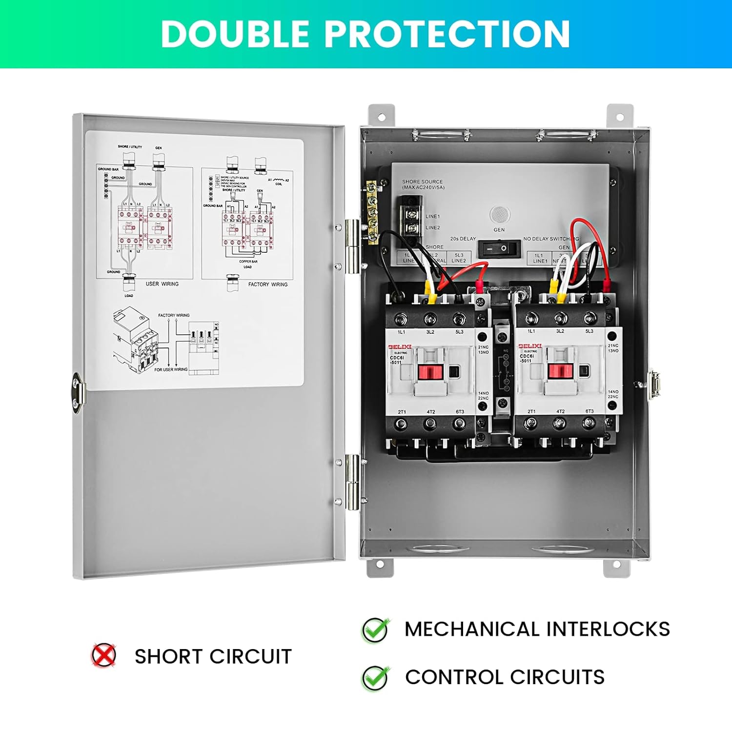
Figure 6.3: Internal components demonstrating the double protection mechanism through mechanical interlocks and control circuits, preventing short circuits.
6.3 Post-Installation Check
- Double-check all wiring connections for tightness and correctness.
- Ensure no bare wires are exposed.
- Close and secure the protective cover of the transfer switch.
7. Operation
The Briidea Automatic Transfer Switch operates with a generator-priority logic, ensuring seamless power management.
7.1 Normal Operation (Utility Power Available)
When utility (shore) power is available, the transfer switch will connect the load to the utility source. The switch continuously monitors the utility power status.
7.2 Generator Operation (Utility Power Outage)
- In the event of a utility power outage, the transfer switch will detect the loss of utility power.
- If connected to a compatible auto-start generator, the generator will automatically start.
- Once the generator is running and its voltage is stable, the built-in MCU circuit will introduce a 20-second delay. This delay ensures the generator's output stabilizes before connecting to the load.
- After the delay, the transfer switch will automatically switch the load to the generator power supply. A green light indicator will illuminate, signifying that generator power is active.
7.3 Return to Utility Power
- When utility power is restored, the transfer switch will detect its presence.
- The switch will automatically transfer the load back to the utility power source.
- The generator will then shut down (if configured for auto-shutdown).
8. Maintenance
Regular maintenance ensures the longevity and reliable operation of your transfer switch.
- Periodic Inspection: Annually, or more frequently in harsh environments, have a qualified electrician inspect the transfer switch. Check for loose connections, signs of corrosion, or physical damage.
- Cleaning: Keep the exterior of the enclosure clean. Use a damp cloth to wipe away dust and debris. Do not use abrasive cleaners or solvents.
- Enclosure Integrity: Ensure the enclosure remains sealed and free from cracks to maintain its IP65 waterproof rating.
- Professional Servicing: Any internal servicing or repair should only be performed by a qualified electrician.
9. Troubleshooting
If you encounter issues with your Briidea Automatic Transfer Switch, refer to the following common troubleshooting steps. Always ensure power is disconnected before inspecting any wiring.
- No Power to Load:
- Check if both utility and generator power sources are active.
- Verify that circuit breakers for both sources and the main load are not tripped.
- Ensure all wiring connections are secure and correct according to the diagram.
- Switch Not Transferring:
- Confirm that the generator is running and producing stable voltage if utility power is out.
- Check for any obstructions or debris preventing the internal contactors from moving freely.
- Allow for the 20-second delay when switching to generator power.
- Green Light Not Illuminating (Generator Power):
- Ensure the generator is providing power and the switch has successfully transferred.
- If the switch is functioning but the light is off, the indicator light itself may be faulty.
- Unusual Noises or Odors:
- Immediately disconnect all power sources.
- Contact a qualified electrician for inspection and repair. Do not attempt to operate the unit.
For issues not resolved by these steps, or for any complex electrical problems, contact a qualified electrician or Briidea customer support.
10. Warranty and Support
Briidea products are manufactured to high-quality standards. For specific warranty information, please refer to the warranty card included with your product or visit the official Briidea website. For technical support, installation assistance, or to report any issues, please contact Briidea customer service through their official channels.
Briidea Customer Service: Please refer to your purchase documentation or the Briidea official website for contact details.
11. Product Application Examples
The Briidea Automatic Transfer Switch is versatile and designed for various high-power applications, including:
- Recreational Vehicles (RVs): Provides automatic switching between shore power and an onboard generator, ensuring continuous power during travel or remote camping.
- Speedboats and Marine Vessels: Manages power sources for essential systems on boats, allowing for seamless transition between dockside power and a marine generator.
- Off-Grid Cabins/Homes: Can be integrated into systems requiring automatic backup power from a generator.

Figure 11.1: The transfer switch positioned near an RV, illustrating its easy installation for recreational vehicle use.
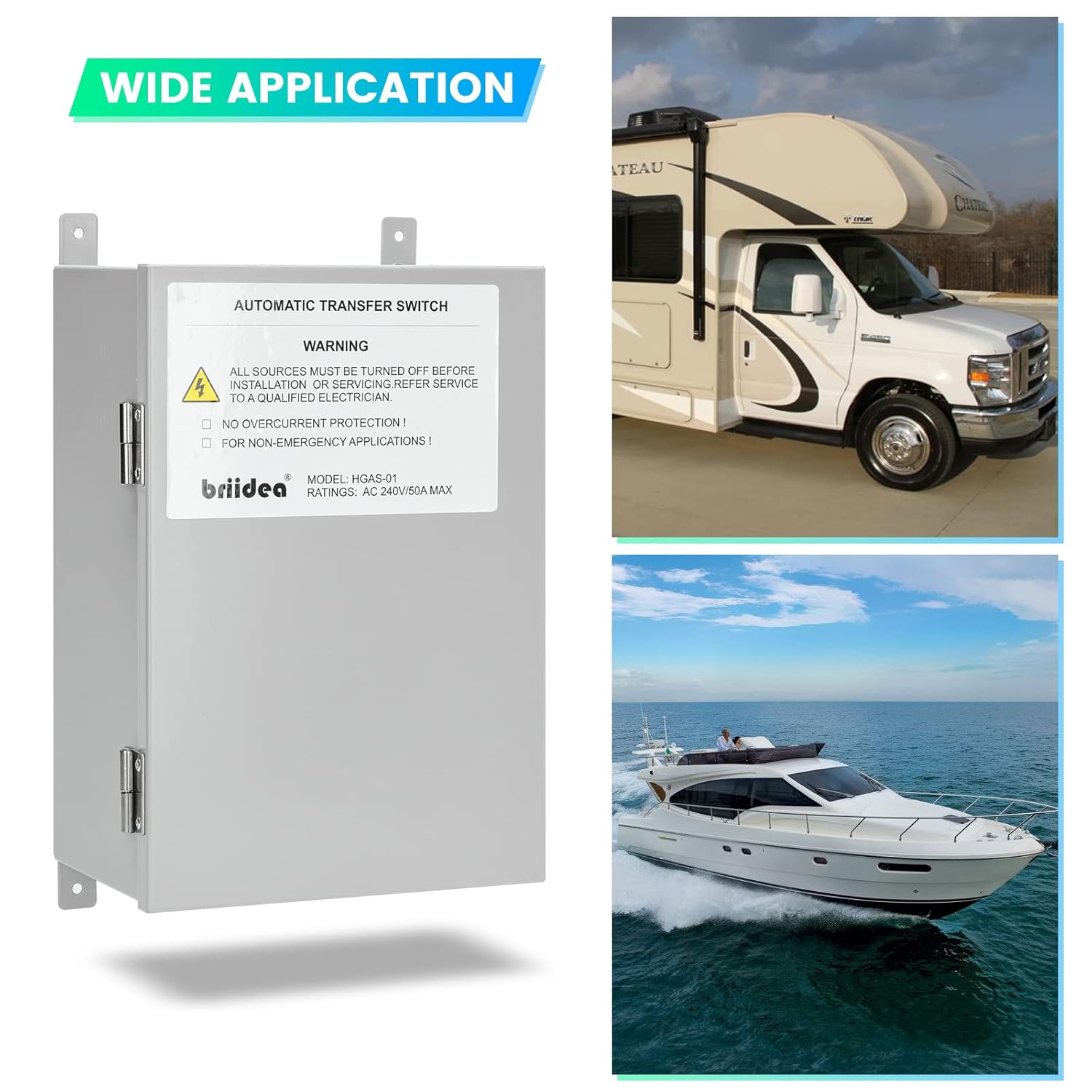
Figure 11.2: The transfer switch shown alongside an RV and a speedboat, emphasizing its suitability for a wide range of applications.