Introduction
This manual provides detailed instructions for the safe and efficient operation, installation, and maintenance of your Wiltec Sand Filter System. Please read this manual thoroughly before operating the unit and keep it for future reference.

Image: The Wiltec Sand Filter System, featuring a prominent blue filter tank and a black self-priming pump, connected by white piping, all mounted on a sturdy black base.
Safety Instructions
Always observe the following safety precautions to prevent injury and damage to the equipment:
- Ensure the power supply matches the specifications of the pump.
- Disconnect power before performing any maintenance or service.
- Do not operate the pump dry.
- Keep children and unauthorized persons away from the filter system.
- Install the system on a level, stable surface.
- Refer to local regulations for proper installation and electrical connections.
Components Overview
The Wiltec Sand Filter System consists of several key components designed for efficient pool water filtration.

Image: An exploded view highlighting the main components of the sand filter system, including the multi-port valve, pressure gauge, bottom drain plug, and the self-priming pump unit.
- Filter Tank: The main vessel where filter sand (or other media) is contained.
- Multi-Port Valve: A 5-way valve controlling the water flow for different operations (filter, backwash, rinse, closed, winter).
- Pressure Gauge: Indicates the internal pressure of the filter, helping to determine when backwashing is needed.
- Self-Priming Pump: Draws water from the pool and pushes it through the filter.
- Drain Opening: Located at the bottom of the tank for easy draining.
- Connecting Hoses/Pipes: For water circulation between the pump, filter, and pool.
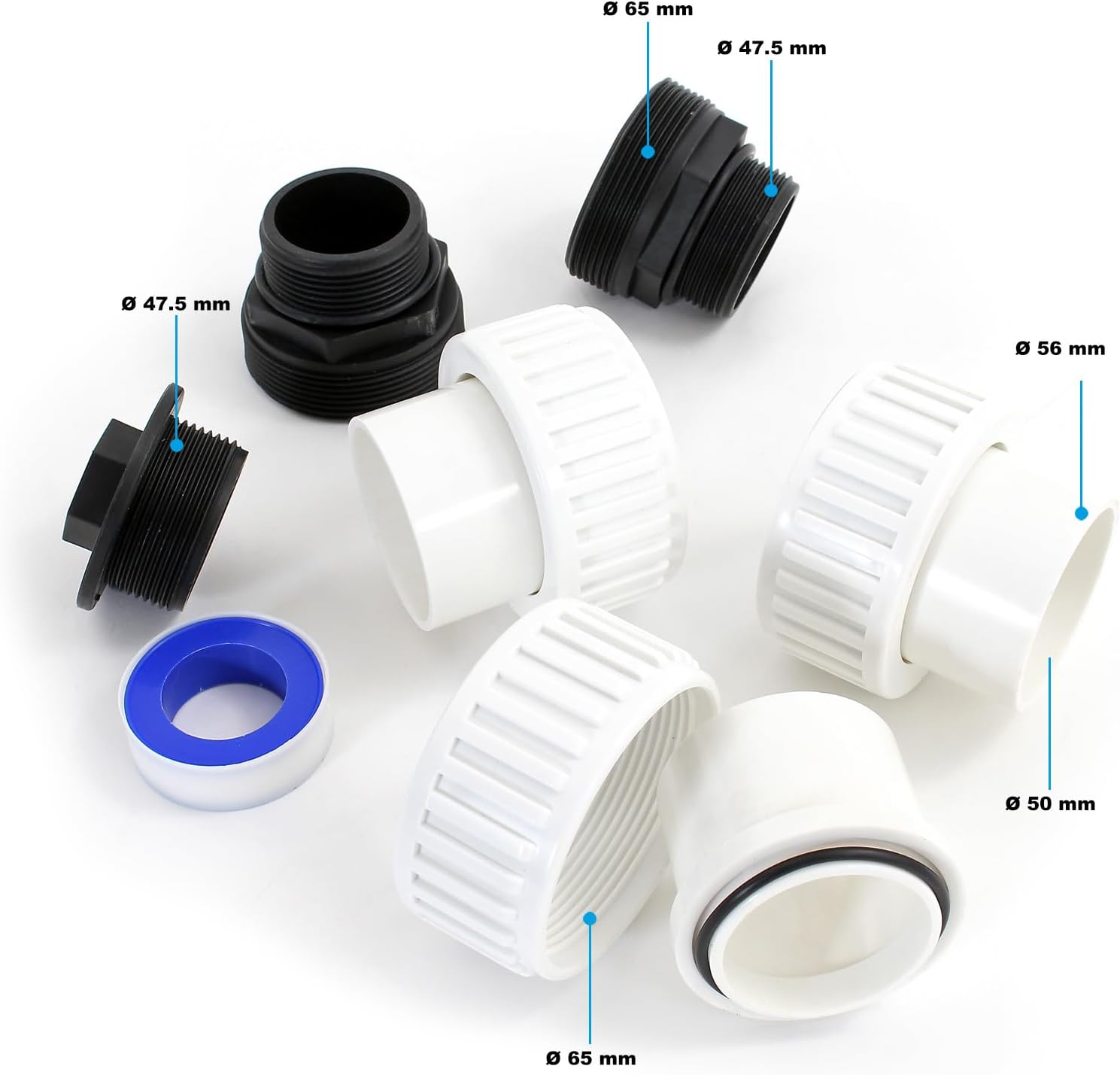
Image: A collection of various connection fittings, adapters, and sealing tape, illustrating the types of plumbing components required for system assembly.
Setup and Installation
Follow these steps for proper assembly and installation of your sand filter system:
- Unpack Components: Carefully remove all parts from the packaging and check against the parts list.
- Position the System: Place the filter system on a firm, level surface, close to the pool and a suitable power outlet. Ensure adequate ventilation.
- Fill the Filter Tank: Add the appropriate amount of filter sand (or other media) to the tank. Refer to the specifications for the correct quantity.
- Attach Multi-Port Valve: Securely attach the multi-port valve to the top of the filter tank. Ensure all seals are correctly seated.
- Connect Pump: Connect the self-priming pump to the filter tank using the provided piping. Ensure all connections are tight to prevent leaks.
- Connect to Pool: Connect the system to your pool's skimmer and return lines. The pump inlet connects to the skimmer, and the filter outlet connects to the return line.
- Electrical Connection: Connect the pump to a grounded electrical outlet. Ensure the circuit is protected by a Residual Current Device (RCD).
- Prime the Pump: Before starting, ensure the pump is filled with water to prime it. This prevents dry running.
Operating Instructions
The multi-port valve allows for various operational modes. Always turn off the pump before changing valve settings.
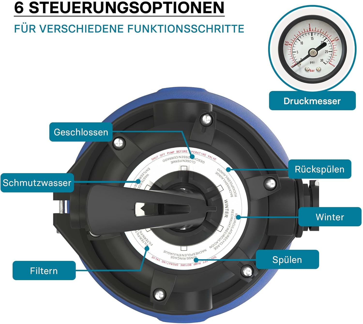
Image: A detailed view of the multi-port valve, clearly labeling its six operational settings: Closed, Dirty Water, Filter, Backwash, Winter, and Rinse, along with the integrated pressure gauge.
- Filter: (Normal Operation) Water is pumped through the filter media, trapping debris, and returned to the pool. This is the primary mode for daily filtration.
- Backwash: (Cleaning Filter) Reverses the water flow through the filter media to dislodge trapped debris, which is then discharged to waste. Perform when pressure gauge indicates high pressure or flow rate decreases.
- Rinse: (After Backwash) Used after backwashing to settle the filter media and flush out any remaining dirty water from the valve, before returning to filter mode.
- Waste/Dirty Water: (Bypass Filter) Water is pumped directly to waste, bypassing the filter. Useful for vacuuming heavy debris directly to waste or lowering pool water level.
- Closed: (System Shut-off) Closes all flow to the filter and pump. Use when performing maintenance or when the system is not in use.
- Winter: (Winterization) Position for draining the system and preparing it for winter storage, preventing damage from freezing.
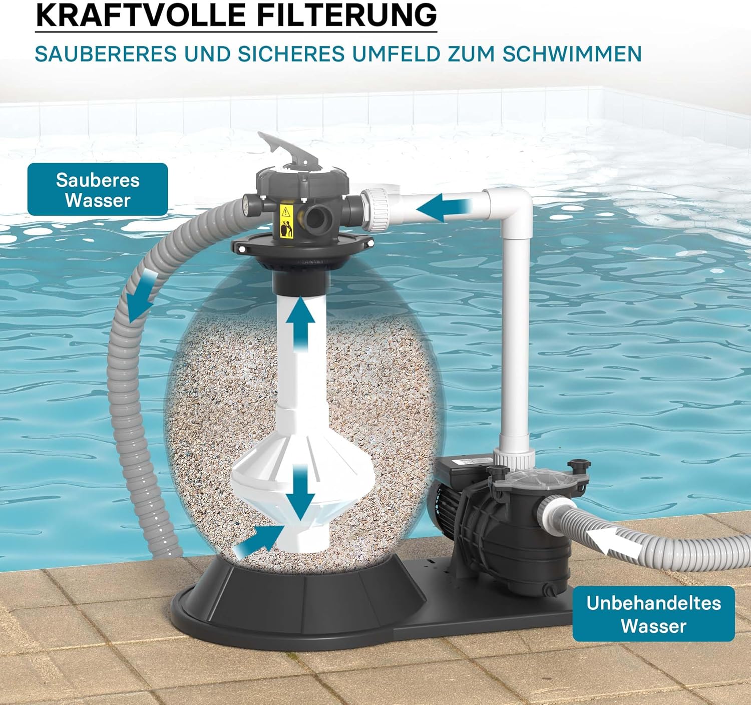
Image: A visual representation of the filtration process, showing untreated water entering the pump, passing through the sand filter, and clean water being returned to the pool, ensuring a cleaner and safer swimming environment.
Maintenance
Regular maintenance ensures optimal performance and longevity of your filter system.
- Backwashing: Backwash the filter regularly, typically when the pressure gauge reads 8-10 PSI above its clean operating pressure, or when pool water clarity decreases.
- Rinsing: Always rinse the filter for 30-60 seconds after each backwash cycle.
- Sand Replacement: Filter sand typically needs replacement every 3-5 years, depending on usage and water quality.
- Pump Basket Cleaning: Periodically clean the pump's strainer basket to remove large debris and ensure proper water flow.
- Winterization: In colder climates, drain the filter tank and pump completely and store in a frost-free area to prevent freezing damage.
Troubleshooting
| Problem | Possible Cause | Solution |
|---|---|---|
| Low Water Flow | Clogged pump basket; Dirty filter sand; Air leak in suction line. | Clean pump basket; Backwash/Rinse filter; Check and seal all connections. |
| Cloudy Pool Water | Insufficient filtration time; Dirty filter sand; Incorrect chemical balance. | Increase filtration time; Backwash/Rinse filter; Test and adjust pool chemistry. |
| Pump Not Priming | Low water level in pump; Air leak; Clogged skimmer/main drain. | Fill pump with water; Check all connections for leaks; Clear obstructions. |
| Water Leaks | Loose connections; Damaged O-rings/gaskets. | Tighten connections; Inspect and replace O-rings/gaskets as needed. |
Specifications
Key technical specifications for the Wiltec Sand Filter System:

Image: An infographic summarizing the key technical specifications of the sand filter pump, including maximum water temperature, material, power consumption, valve type, and maximum flow rate.
| Attribute | Value |
|---|---|
| Model Number | 63347 |
| Power | 750 W |
| Filter Tank Capacity | 71 L |
| Pump Capacity (Flow Rate) | Up to 20,000 l/h |
| Max. Delivery Height | 14 m |
| Material | Plastic |
| Product Dimensions | 60 x 50.5 x 85 cm |
| Product Weight | 18.56 kg |
| Drive Type | Corded Electric |
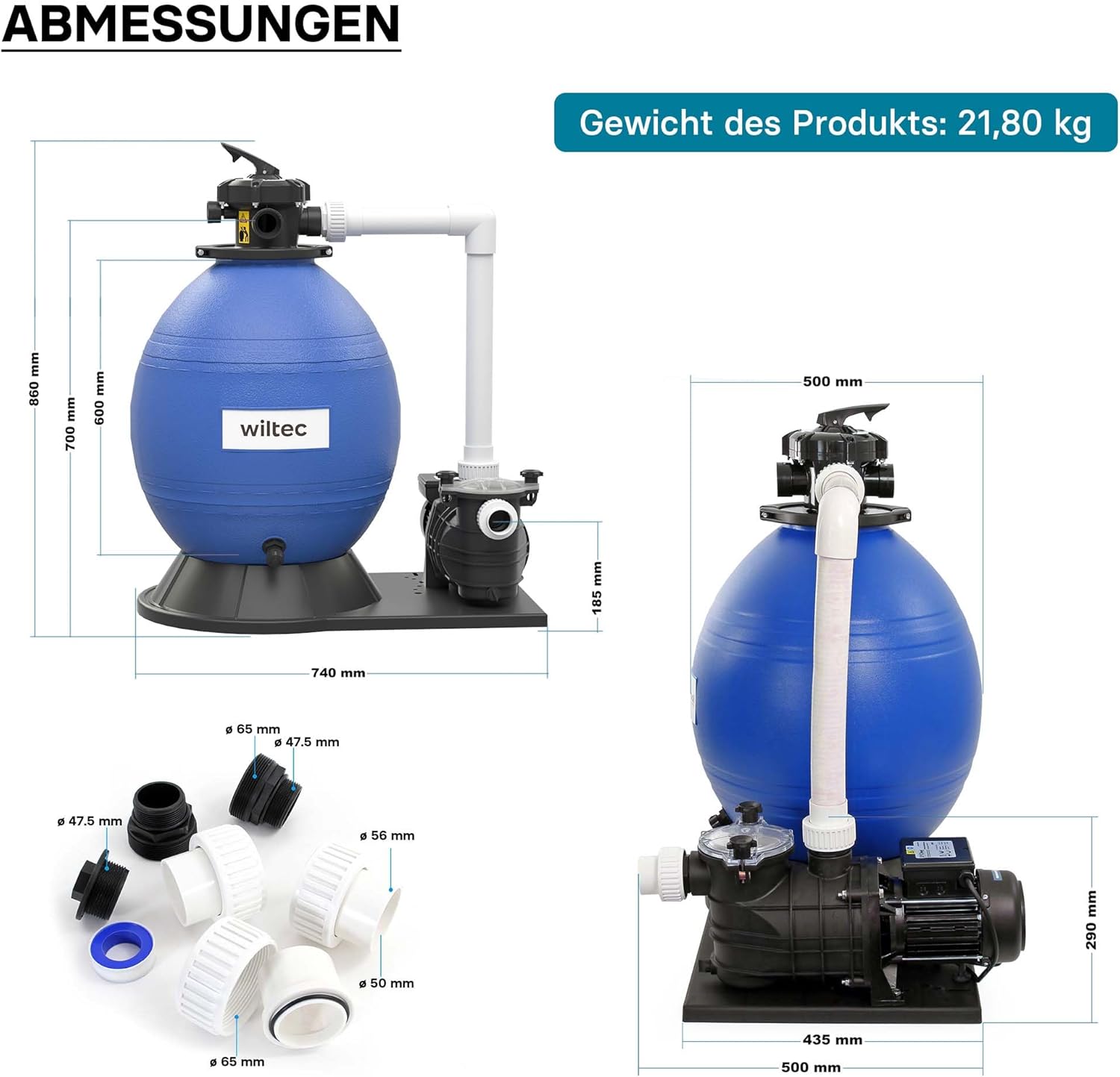
Image: A technical drawing providing precise dimensions of the sand filter system, including height, width, and depth measurements for both the tank and pump components.
Warranty and Support
For warranty information, technical support, or spare parts, please refer to the original product documentation or contact Wiltec customer service directly. Contact details can typically be found on the manufacturer's website or on your purchase receipt.
Wiltec Wildanger Technik GmbH
Website: www.wiltec.de