1. Introduction
The VAR TECH V 68 is an auto-ranging digital multimeter designed for precise electrical measurements. It features True RMS capability, a 4000-count HD display with backlight, and a robust, shockproof construction. This instrument is equipped to measure AC/DC voltage up to 1000V/750V, AC/DC current up to 10A, resistance, capacitance, frequency, and temperature. Additional functions include Non-Contact Voltage (NCV) detection, transistor (hFE) testing, continuity, diode testing, data hold, and auto power-off. Safety is enhanced with double fuse overload protection.

Figure 1.1: Front view of the VAR TECH V 68 Digital Multimeter, showcasing its display, rotary dial, and function buttons.
2. Safety Information
To ensure safe operation and prevent damage to the meter, please read and follow all safety instructions carefully. This device complies with CE standards.
- Always ensure the test leads are properly connected and the rotary switch is set to the correct range before making any measurements.
- Do not attempt to measure voltages or currents exceeding the specified maximum limits (1000V DC, 750V AC, 10A AC/DC).
- Exercise extreme caution when working with live circuits. High voltages can cause severe injury or death.
- Never connect the meter to a voltage source when the rotary switch is set to current, resistance, continuity, diode, capacitance, or frequency modes.
- Replace batteries and fuses only with the specified types and ratings.
- Do not operate the meter if it appears damaged or if the protective case is removed.
- Keep hands and fingers behind the probe barriers during measurements.
3. Product Features Overview
The VAR TECH V 68 is designed for versatility and reliability in various electrical testing scenarios. Key features include:
- True RMS Measurement: Provides accurate readings for non-sinusoidal waveforms.
- Auto/Manual Ranging: Automatically selects the appropriate measurement range or allows manual selection.
- 4000 Counts HD Display: Clear, high-definition display with backlight for easy reading in various lighting conditions.
- Wide Measurement Ranges: Measures up to 1000V DC, 750V AC, 10A AC/DC, Resistance up to 40 MΩ, Capacitance up to 100 mF, Frequency up to 20 MHz, and Temperature from -20°C to 1000°C.
- Non-Contact Voltage (NCV): Detects AC voltage without direct contact, enhancing safety.
- Flashlight Function: Integrated flashlight for illumination in dark work areas.
- Double Fuse Overload Protection: Built-in 100mA/250V and 10A/250V fuses protect the meter from current overloads.
- Shockproof Construction: Durable design with an anti-drop protective case.
- Data Hold: Freezes the displayed reading for convenient recording.
- Auto Power Off: Conserves battery life by automatically turning off after a period of inactivity.
- Low Battery Indicator: Alerts when batteries need replacement.

Figure 3.1: Graphic illustrating the key features of the VAR TECH V 68 Multimeter, including 4000 counts, HD backlight, auto/manual ranging, temperature, frequency, capacitance, diode, continuity, NCV, data hold, and flashlight.
Video 3.1: A brief overview demonstrating the VAR TECH V 68 Digital Multimeter's features and capabilities.
4. Component Identification
Familiarize yourself with the main components of your VAR TECH V 68 multimeter:
- LCD Display: Shows measurement readings, units, and function indicators.
- Rotary Switch: Used to select the desired measurement function.
- Function Buttons:
- Hz/DUTY/SELECT: Toggles between frequency/duty cycle or selects sub-functions.
- RANGE: Switches between auto-ranging and manual ranging.
- REL: Activates relative measurement mode.
- HOLD/BL: Holds the current reading on the display and activates/deactivates backlight.
- Input Jacks:
- VΩHz: Input for voltage, resistance, frequency, capacitance, diode, and continuity measurements.
- mAµA: Input for milliampere and microampere current measurements.
- 10A: Input for 10 Ampere current measurements.
- COM: Common (negative) input for all measurements.
- NCV Sensor: Located at the top of the meter for non-contact voltage detection.
- Flashlight: Located at the top rear of the meter.

Figure 4.1: Close-up of the test lead jack design and the large screen backlight feature on the VAR TECH V 68 Multimeter.
5. Getting Started
5.1. Battery Installation
The VAR TECH V 68 requires four (4) AAA batteries for operation. These are typically included with the product.
- Ensure the multimeter is turned OFF.
- Locate the battery compartment cover on the back of the meter.
- Use a screwdriver to open the battery compartment.
- Insert four new AAA batteries, observing the correct polarity (+/-) as indicated inside the compartment.
- Replace the battery compartment cover and secure it with the screw.
5.2. Connecting Test Leads
Always connect the black test lead to the COM jack. Connect the red test lead to the appropriate input jack based on the measurement type:
- For Voltage, Resistance, Capacitance, Frequency, Diode, and Continuity: Connect the red lead to the VΩHz jack.
- For Current (mA/µA): Connect the red lead to the mAµA jack.
- For High Current (10A): Connect the red lead to the 10A jack.
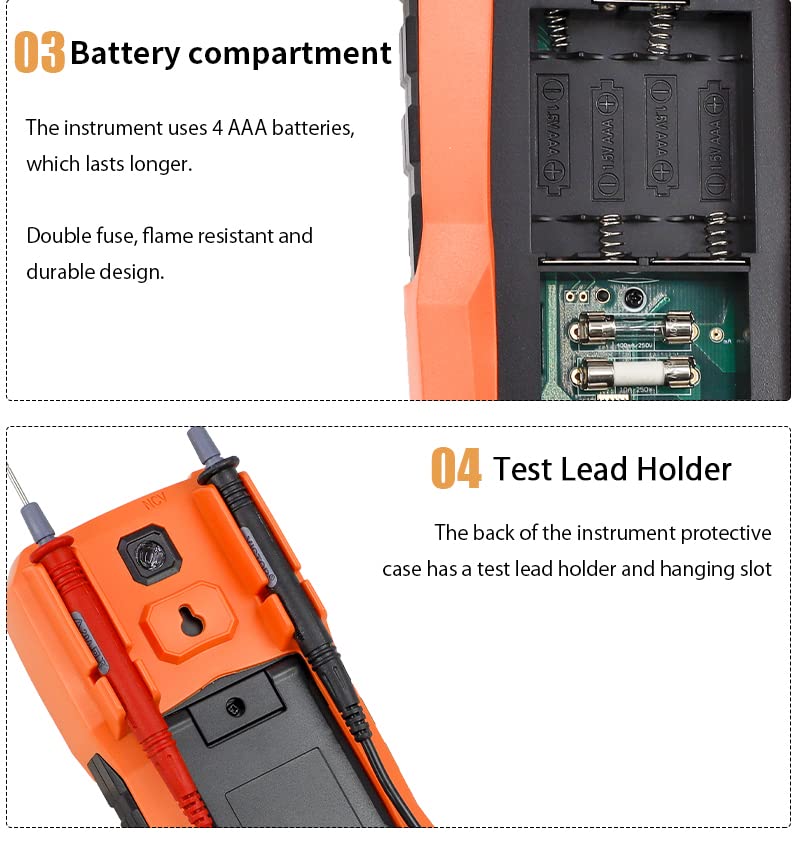
Figure 5.1: Rear view showing the battery compartment and the integrated test lead holder on the VAR TECH V 68 Multimeter.
6. Operating Instructions
Turn the rotary switch to the desired function. The meter will typically auto-range. Use the SELECT button for sub-functions if applicable.
6.1. Voltage Measurement (AC/DC)
- Set the rotary switch to V~ (AC Voltage) or V- (DC Voltage).
- Connect the black test lead to the COM jack and the red test lead to the VΩHz jack.
- Connect the probes across the circuit or component to be measured.
- Read the voltage value on the display.
6.2. Current Measurement (AC/DC)
Caution: Never connect the meter in parallel to a voltage source when measuring current.
- Set the rotary switch to A~ (AC Current) or A- (DC Current).
- For currents up to 400mA, connect the red lead to the mAµA jack. For currents up to 10A, connect the red lead to the 10A jack. Connect the black lead to the COM jack.
- Open the circuit where current is to be measured and connect the meter in series.
- Read the current value on the display.
6.3. Resistance Measurement
- Set the rotary switch to Ω.
- Connect the black test lead to the COM jack and the red test lead to the VΩHz jack.
- Connect the probes across the component to be measured. Ensure the circuit is de-energized.
- Read the resistance value on the display.
6.4. Continuity Test
- Set the rotary switch to the continuity/diode symbol (often shared with resistance). Use the SELECT button if necessary to choose continuity.
- Connect the black test lead to the COM jack and the red test lead to the VΩHz jack.
- Connect the probes across the circuit or component.
- If continuity exists (resistance below a certain threshold), the buzzer will sound.
6.5. Diode Test
- Set the rotary switch to the continuity/diode symbol. Use the SELECT button if necessary to choose diode test.
- Connect the black test lead to the COM jack and the red test lead to the VΩHz jack.
- Connect the red probe to the anode and the black probe to the cathode of the diode. The display will show the forward voltage drop.
- Reverse the probes. The display should show 'OL' (Open Loop) for a good diode.
6.6. Capacitance Measurement
- Set the rotary switch to the capacitance symbol (often shared with frequency). Use the SELECT button if necessary.
- Connect the black test lead to the COM jack and the red test lead to the VΩHz jack.
- Discharge the capacitor before connecting the probes.
- Connect the probes across the capacitor.
- Read the capacitance value on the display.
6.7. Frequency and Duty Cycle Measurement
- Set the rotary switch to the Hz/DUTY symbol (often shared with capacitance). Use the SELECT button to toggle between Frequency (Hz) and Duty Cycle (%).
- Connect the black test lead to the COM jack and the red test lead to the VΩHz jack.
- Connect the probes across the signal source.
- Read the frequency or duty cycle value on the display.
6.8. Temperature Measurement
- Set the rotary switch to the °C/°F symbol. Use the SELECT button to toggle between Celsius and Fahrenheit.
- Connect the temperature probe to the VΩHz and COM jacks, observing polarity.
- Place the tip of the temperature probe on or near the object whose temperature is to be measured.
- Read the temperature value on the display.
6.9. Non-Contact Voltage (NCV) Detection
- Set the rotary switch to NCV.
- Move the top of the meter (where the NCV sensor is located) close to the conductor or outlet.
- If AC voltage is detected (typically 48-220V), the red indicator light will flash, and the buzzer will emit a beep sound.
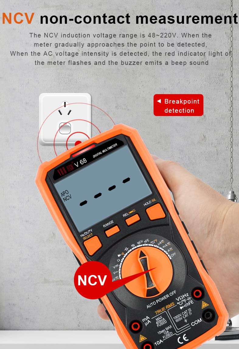
Figure 6.1: Demonstration of the NCV (Non-Contact Voltage) function, showing the multimeter detecting voltage near an electrical outlet.
6.10. Transistor (hFE) Test
- Set the rotary switch to hFE.
- Insert the transistor leads into the appropriate holes of the multifunction test socket (PNP or NPN).
- Read the hFE value (DC current gain) on the display.
6.11. Special Functions
- Data Hold: Press the 'HOLD/BL' button briefly to freeze the current reading on the display. Press again to release.
- Backlight: Press and hold the 'HOLD/BL' button to turn the display backlight ON or OFF.
- Flashlight: Press the dedicated flashlight button on the side/rear of the meter to activate the flashlight.
- Relative Measurement (REL): Press the 'REL' button to store the current reading as a reference. Subsequent measurements will be displayed as the difference from this reference value. Press again to exit.
- Auto Power Off (APO): The meter will automatically power off after approximately 15 minutes of inactivity to conserve battery life. To disable APO, hold down the 'SELECT' button while turning the meter ON.
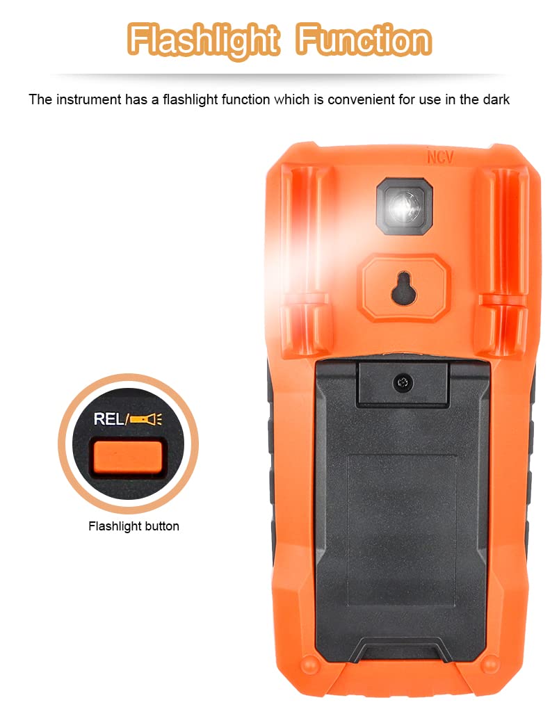
Figure 6.2: Rear view of the VAR TECH V 68 Multimeter highlighting the flashlight function and its activation button.
7. Maintenance
7.1. Battery Replacement
When the low battery indicator appears on the display, replace the batteries as described in Section 5.1.
7.2. Fuse Replacement
The VAR TECH V 68 is equipped with double fuse protection. If the meter fails to measure current, the fuse may need replacement. Always replace with fuses of the specified type and rating:
- 100mA/250V fuse for mA/µA range.
- 10A/250V fuse for 10A range.
- Ensure the multimeter is turned OFF and test leads are disconnected.
- Open the battery compartment cover (refer to Section 5.1).
- Carefully remove the old fuse(s) and replace with new ones of the correct rating.
- Replace the battery compartment cover and secure it.

Figure 7.1: Internal view of the VAR TECH V 68 Multimeter's double fuse protection, showing the 100mA and 10A fuses.
7.3. Cleaning
Wipe the meter with a damp cloth and mild detergent. Do not use abrasives or solvents.
8. Troubleshooting
If the meter does not function correctly, check the following:
- No display or dim display: Check battery charge. Replace if low.
- Incorrect readings: Ensure the rotary switch is set to the correct function and range. Check test lead connections.
- No current measurement: Check the current fuses (refer to Section 7.2).
- 'OL' displayed: Indicates an overload or open circuit. Ensure the measurement range is appropriate or the circuit is complete.
- Meter does not turn on: Check battery installation and charge.
9. Specifications
| Parameter | Specification |
|---|---|
| Display | 4000 Counts LCD with Backlight |
| DC Voltage Range | Up to 1000V |
| AC Voltage Range | Up to 750V (True RMS) |
| DC Current Range | Up to 10A |
| AC Current Range | Up to 10A |
| Resistance Range | 400 Ω to 40 MΩ |
| Capacitance Range | 6 nF to 100 mF |
| Frequency Range | 10 Hz to 20 MHz |
| Temperature Range | -20 °C to 1000 °C |
| Special Features | NCV, Torch, Double Fuse Overload Protection, Data Hold, Auto Power Off, Relative Measurement, Transistor (hFE) Test |
| Power Source | 4 x AAA Batteries (included) |
| Dimensions (L x W x H) | 18.6 x 9.2 x 5.2 cm |
| Item Weight | 400 Grams |
| Included Components | Test leads, temperature probes, multifunction test socket, batteries |
| Safety Rating | CE |
10. Warranty and Support
VAR TECH products are manufactured to high-quality standards. This product typically comes with a standard manufacturer's warranty against manufacturing defects. For specific warranty terms, duration, and support inquiries, please refer to the warranty card included with your product or contact VAR TECH customer service directly. Keep your purchase receipt as proof of purchase for warranty claims.
Manufacturer: V A R TECH, www.var-tech.com


