1. Introduction
This manual provides detailed instructions for the safe and effective operation of the VAR TECH Digital Multimeter V 92. This auto-ranging, True RMS multimeter is designed for precise electrical measurements in various applications. Please read this manual thoroughly before use to ensure proper functionality and safety.

Figure 1.1: Front view of the VAR TECH Digital Multimeter V 92, displaying its screen, function dial, and input jacks.
2. Safety Information
WARNING: To avoid electric shock or personal injury, read and understand all safety information before using this multimeter.
- Always ensure the test leads are properly connected and the function dial is set to the correct range before making any measurements.
- Do not measure voltages exceeding 600V AC/DC.
- Do not measure current exceeding 10A AC/DC.
- Exercise extreme caution when working with live circuits.
- Inspect test leads for damage before each use. Replace damaged leads immediately.
- Do not operate the multimeter if it appears damaged or is not functioning properly.
- Adhere to local and national safety codes.
3. Product Overview
3.1 Key Features
- True RMS measurement for accurate readings on non-sinusoidal waveforms.
- 6000 counts HD display with backlight for clear visibility.
- Auto-ranging for simplified operation.
- Non-Contact Voltage (NCV) detection.
- Integrated flashlight for illumination in dark areas.
- Overload protection and shockproof design for durability and safety.
- Data Hold function to freeze readings on the display.
- Automatic power-off to conserve battery life.

Figure 3.1: Overview of the VAR TECH V 92 Digital Multimeter's main features, including True RMS, 6000 counts, NCV, and overload protection.
3.2 Ergonomic Design
The VAR TECH V 92 is designed for comfortable and secure handling, making it suitable for extended use. Its compact size and robust construction contribute to its portability and durability.

Figure 3.2: The multimeter shown comfortably held in a hand, illustrating its ergonomic and handy size.
3.3 Integrated Stand and Test Lead Holder
The multimeter features a built-in kickstand for convenient hands-free operation and a test lead holder on the back for organized storage and transport.

Figure 3.3: The multimeter's bracket design allows for easy placement and viewing of data.

Figure 3.4: The test lead holder on the back provides convenient storage and portability for the test leads.
4. Setup
4.1 Included Components
The VAR TECH V 92 Digital Multimeter package includes:
- VAR TECH V 92 Digital Multimeter
- Test Leads (Red and Black)
- Type-K Thermocouple Probe
- AAA Batteries (2 included)
- User Manual
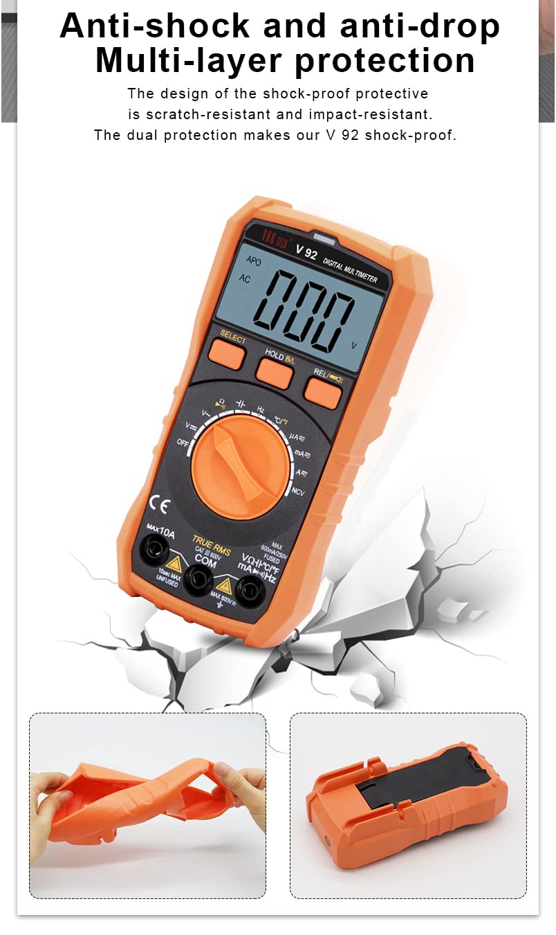
Figure 4.1: The image displays the multimeter, test leads, and battery compartment, representing the included components.
4.2 Battery Installation
- Ensure the multimeter is powered off.
- Locate the battery compartment cover on the back of the device.
- Use a screwdriver to open the battery compartment.
- Insert two AAA batteries, observing the correct polarity (+/-).
- Replace the battery compartment cover and secure it with the screw.
4.3 Connecting Test Leads
Connect the test leads to the appropriate input jacks on the multimeter:
- Insert the black test lead into the COM (Common) jack.
- For most voltage, resistance, continuity, capacitance, and frequency measurements, insert the red test lead into the VΩHzCAP jack.
- For current measurements (up to 10A), insert the red test lead into the 10A jack.
- For milliampere/microampere current measurements, insert the red test lead into the mAµA jack.

Figure 4.2: The precise contact design of the test lead jacks ensures accurate and quick measurements.
5. Operating Instructions
Turn the rotary dial to select the desired measurement function.
5.1 Voltage Measurement (AC/DC)
- Set the rotary dial to the V~ (AC Voltage) or V- (DC Voltage) position. The multimeter will auto-range.
- Connect the test leads in parallel to the circuit or component under test.
- Read the voltage value on the display.
5.2 Current Measurement (AC/DC)
- Set the rotary dial to the A~ (AC Current) or A- (DC Current) position, or mAµA for smaller currents.
- Connect the test leads in series with the circuit. Ensure the red lead is in the appropriate 10A or mAµA jack.
- Read the current value on the display.
5.3 Resistance Measurement (Ω)
- Set the rotary dial to the Ω position.
- Ensure the circuit is de-energized before measuring resistance.
- Connect the test leads across the component to be measured.
- Read the resistance value on the display.
5.4 Continuity Test
- Set the rotary dial to the Ω position and press the SELECT button until the continuity symbol (speaker icon) appears.
- Connect the test leads across the circuit or component.
- A continuous beep indicates continuity (low resistance).
5.5 Capacitance Measurement (CAP)
- Set the rotary dial to the CAP position.
- Ensure the capacitor is discharged before measurement.
- Connect the test leads across the capacitor terminals.
- Read the capacitance value on the display.
5.6 Frequency Measurement (Hz)
- Set the rotary dial to the Hz position.
- Connect the test leads to the signal source.
- Read the frequency value on the display.
5.7 Temperature Measurement (°C/°F)
- Set the rotary dial to the °C/°F position.
- Connect the Type-K thermocouple probe to the input jacks, observing polarity.
- Place the probe tip on or near the object whose temperature is to be measured.
- Read the temperature value on the display. Press SELECT to switch between Celsius and Fahrenheit.
5.8 Non-Contact Voltage (NCV) Detection
- Set the rotary dial to the NCV position.
- Move the top of the multimeter near a live AC voltage source.
- The meter will indicate the presence of AC voltage with an audible beep and flashing red indicator light.
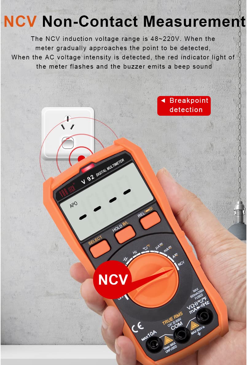
Figure 5.1: The NCV function detects AC voltage without direct contact, indicated by a flashing light and beep.
5.9 Data Hold
Press the HOLD B/L button briefly to freeze the current reading on the display. Press it again to release the hold function. A long press of the HOLD B/L button activates the backlight.
5.10 Auto Power Off
The multimeter will automatically power off after approximately 15 minutes of inactivity to conserve battery life. To disable this feature temporarily, hold down the SELECT button while turning the meter on.
6. Maintenance
6.1 Cleaning
Wipe the case with a damp cloth and mild detergent. Do not use abrasives or solvents. Ensure the device is dry before use.
6.2 Battery Replacement
When the battery indicator appears on the display, replace the batteries as described in Section 4.2. Always use two new AAA batteries.
6.3 Fuse Replacement
The multimeter is equipped with an intelligent fuse protection system. If the current measurement function fails, the fuse may need replacement. Refer to the specifications for the correct fuse type (600mA/250V, 5x20mm).

Figure 6.1: The intelligent fuse protection system helps protect the instrument from overcurrents.
6.4 Shockproof Design
The VAR TECH V 92 features a multi-layer shockproof and impact-resistant shell, providing enhanced durability and protection against accidental drops.

Figure 6.2: The robust design provides multi-layer protection against physical impact.
7. Troubleshooting
- No Display: Check battery installation and ensure batteries are not depleted. Replace if necessary.
- Incorrect Readings: Verify the function dial is set to the correct measurement type and range. Ensure test leads are properly connected and not damaged.
- No Continuity Beep: Confirm the continuity function is selected. Check if the circuit or component has high resistance.
- Current Measurement Failure: Check the fuse as described in Section 6.3.
- Auto Power Off Too Soon: The auto power-off feature activates after 15 minutes of inactivity. To temporarily disable it, hold the SELECT button while powering on.
8. Specifications
| Parameter | Specification |
|---|---|
| Display | 6000 Counts, HD with Backlight |
| True RMS | Yes |
| DC Voltage Range | 600mV to 600V |
| AC Voltage Range | 600mV to 600V |
| DC Current Range | 600µA to 10A |
| AC Current Range | 600µA to 10A |
| Resistance Range | 600Ω to 60MΩ |
| Capacitance Range | 10nF to 2mF |
| Frequency Measurement | Yes (in ACV range) |
| Temperature Range | -20°C to 1000°C (-4°F to 1832°F) |
| Non-Contact Voltage (NCV) | Yes |
| Overload Protection | Yes |
| Power Source | 2 x AAA Batteries (included) |
| Dimensions (L x W x H) | 14.6 x 7.2 x 5 cm |
| Weight | 250 Grams |
| Safety Rating | CE |
9. Warranty and Support
The VAR TECH Digital Multimeter V 92 comes with a 1-year warranty against manufacturing defects. For technical support or warranty claims, please contact VAR TECH customer service through the official website or your point of purchase. Please retain your purchase receipt as proof of purchase.


