1. Introduction
The LoraTap Wireless Roller Shutter Module (Model SC511SC) with RF Remote Control provides a convenient and efficient solution for controlling motorized roller shutters, blinds, and awnings. This system operates on an 868MHz radio frequency, ensuring stable and reliable communication without the need for Wi-Fi or Bluetooth connectivity. It is designed to be compatible with existing traditional wall switches, allowing for both manual and remote control operation.
This manual provides detailed instructions for the installation, operation, and maintenance of your LoraTap Wireless Roller Shutter Module and its accompanying RF remote control.
2. Package Contents
Please verify that all items listed below are included in your package:
- 1 x LoraTap RF Roller Shutter Module (SC511SC)
- 1 x 3-Button RF Remote Control
- 1 x Key Cord
- 1 x Screwdriver
- Several Screws for installation
- 3 x Wiring Cables
- 1 x Wall Mount Bracket for Remote Control
- 2 x Double-Sided Adhesive Tapes
- 1 x User Guide (this manual)

Figure 2.1: Contents of the LoraTap Wireless Roller Shutter Module package, including the module, remote, and accessories.
3. Specifications
| Feature | Specification |
|---|---|
| Model Number | SC511SC |
| Operating Voltage | 100-250V AC |
| Frequency | 50/60Hz |
| Max. Load Power | 300W |
| Operating Current | 1A |
| Module Dimensions (LxWxH) | 48 x 47 x 22 mm |
| Remote Control Dimensions (LxWxH) | 90 x 30 x 10 mm |
| Wireless Technology | 868MHz RF |
| Indoor Remote Range | Up to 30 meters (through walls) |
| Outdoor Remote Range | Up to 200 meters |
| Compatible Motor Type | 4-wire motor (with Neutral wire) |

Figure 3.1: Physical dimensions of the LoraTap module and remote control.
4. Safety Information and Precautions
Please read and understand all safety instructions before installation and use. Improper installation can lead to electric shock, fire, or other hazards.
- Professional Installation Recommended: Electrical work should be performed by a qualified electrician.
- Power Off: Always disconnect power at the circuit breaker before installing or servicing the module.
- Voltage Compatibility: Ensure the module's operating voltage (100-250V AC) matches your electrical system.
- Motor Compatibility: This module is designed for 4-wire motors only (typically with Blue, Brown, Black, Green/Yellow wires). A neutral wire is required for operation. Do not attempt to connect to 3-wire motors.
- Load Capacity: Do not exceed the maximum load power of 300W.
- Indoor Use: The module is intended for indoor use in dry environments.

Figure 4.1: Motor compatibility and wiring color codes. Ensure your motor has 4 wires including a neutral wire.
5. Installation
5.1 Pre-Installation Checklist
- Ensure power is OFF at the main circuit breaker.
- Confirm your roller shutter/blind motor is a 4-wire type.
- Verify that your wall switch box has sufficient depth (minimum 60mm recommended) to accommodate the module.
5.2 Wiring Diagram
Follow the wiring diagram carefully. Incorrect wiring can damage the module or motor.

Figure 5.1: Wiring connections for the LoraTap SC511SC module.
Wiring Steps:
- Connect the Live (L) and Neutral (N) input wires from your power supply to the corresponding 'Input AC~' terminals on the module.
- Connect the motor's Neutral (N) wire to the 'Output N' terminal on the module.
- Connect the motor's 'Up' wire (e.g., Brown) to the 'L1' terminal on the module.
- Connect the motor's 'Down' wire (e.g., Black) to the 'L2' terminal on the module.
- If using a traditional wall switch, connect the switch's Live (L) input to the 'L' terminal on the module.
- Connect the switch's 'Up' output to the 'S1' terminal on the module.
- Connect the switch's 'Down' output to the 'S2' terminal on the module.
- Ensure all connections are secure and insulated.
5.3 Physical Installation
The compact design of the module allows it to be installed directly into most standard wall switch boxes. Ensure there is enough space for the module and wiring.

Figure 5.2: Recommended wall box depth for module installation.
- After wiring, carefully place the module into the wall box.
- Re-attach the traditional wall switch (if applicable) over the module.
- Restore power at the circuit breaker.

Figure 5.3: Module installed behind a traditional wall switch.
6. Operating Instructions
6.1 Pairing the Remote Control
The remote control and module are typically pre-paired from the factory. If re-pairing is needed or for adding additional remotes:
- Press and hold the 'Pairing Button' on the module for approximately 3 seconds until the indicator light flashes.
- Within 10 seconds, press any button on the remote control you wish to pair.
- The indicator light on the module will stop flashing, indicating successful pairing.
6.2 Basic Operation
Once installed and paired, you can control your roller shutters/blinds using either the traditional wall switch or the RF remote control.
- Using the Remote Control:
Up Button (▲): Press to open/raise the roller shutter.
Down Button (▼): Press to close/lower the roller shutter.
Stop Button (▮▮): Press to stop the roller shutter at any desired position. - Using the Traditional Wall Switch:
A short press on the 'Up' or 'Down' button of your traditional switch will initiate the movement. A second short press will stop the movement.

Figure 6.1: LoraTap module and remote control.
6.3 Remote Control Range and Portability
The 868MHz RF technology provides an extended and stable control range. The remote control can be used as a portable device or mounted on a wall using the provided bracket and adhesive tapes/screws.
- Indoor Range: Up to 30 meters, capable of passing through walls, windows, and ceilings.
- Outdoor Range: Up to 200 meters in open areas.
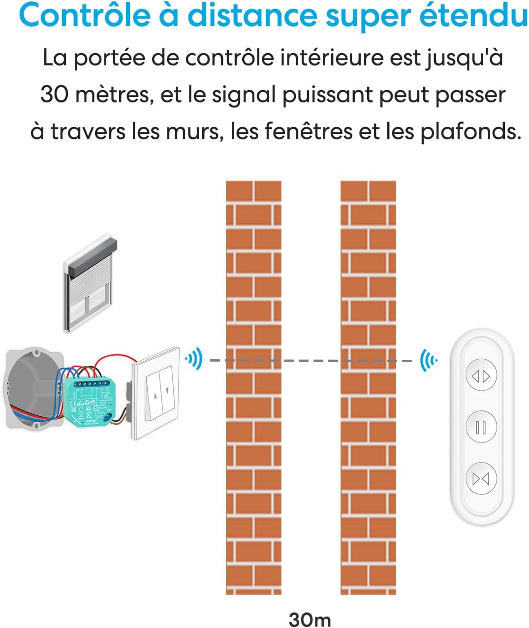
Figure 6.2: Remote control range capability.

Figure 6.3: Remote control portability and mounting options.
7. Maintenance
The LoraTap Wireless Roller Shutter Module requires minimal maintenance.
- Cleaning: Wipe the remote control and any exposed parts of the module with a soft, dry cloth. Do not use abrasive cleaners or liquids.
- Battery Replacement (Remote Control): If the remote control's range decreases or it becomes unresponsive, the battery may need replacement. Refer to the remote control's specific instructions for battery type and replacement procedure.
- Module Access: For any maintenance on the module itself, always disconnect power at the circuit breaker first.
8. Troubleshooting
If you encounter issues with your LoraTap Wireless Roller Shutter Module, refer to the following common problems and solutions:
| Problem | Possible Cause | Solution |
|---|---|---|
| Module not responding to remote control. | Remote not paired, remote battery low, module not powered. | Re-pair the remote control (Section 6.1). Replace remote battery. Check power supply to the module. |
| Roller shutter does not move or moves intermittently. | Incorrect wiring, motor issue, module overload. | Verify wiring according to Figure 5.1. Check motor for faults. Ensure motor power does not exceed 300W. |
| Limited remote control range. | Obstructions, interference, low remote battery. | Ensure no major metal obstructions. Replace remote battery. |
| Traditional wall switch not working. | Incorrect wiring to S1/S2 terminals, switch fault. | Check wiring to S1/S2 terminals (Figure 5.1). Test the traditional switch independently if possible. |
9. Application Scenarios
The LoraTap Wireless Roller Shutter Module is versatile and can be used in various settings for convenient control of motorized window coverings and awnings.

Figure 9.1: Diverse application examples for the LoraTap module.

Figure 9.2: Ease of use for all ages and situations.
10. Warranty and Support
LoraTap products are designed for reliability and performance. For warranty information or technical support, please refer to the contact details provided with your purchase or visit the official LoraTap website. Keep your purchase receipt as proof of purchase for warranty claims.
Online Resources: For additional support, FAQs, and product updates, please visit the LoraTap Brand Store on Amazon.


