1. Introduction
The Klein Tools MM720 is an automatically ranging True Root Mean Squared (TRMS) digital multimeter designed for precise electrical measurements. This device measures AC/DC voltage, AC/DC current, and resistance. Additionally, it offers functions for measuring temperature, capacitance, frequency, duty-cycle, diodes, and continuity. Its high-visibility, reverse-contrast LCD display features an optical sensor that automatically adjusts for optimal viewability in various lighting conditions.
This manual provides essential information for the safe and effective use of your MM720 Digital Multimeter. Please read it thoroughly before operation and retain it for future reference.
2. Safety Information
Always adhere to safety precautions when using electrical test equipment to prevent injury or damage to the meter. Observe all local and national safety codes.
- Hazardous Voltage: Be aware of hazardous voltages. Contact with live circuits can result in severe injury or death.
- Personal Protective Equipment: Always wear approved eye protection and other personal protective equipment (PPE) when working near live electrical circuits.
- Insulated Test Leads: Use only insulated test leads with finger guards. Ensure they are in good condition, free from cracks or damage.
- CAT Rating: This meter is rated CAT IV 600V and CAT III 1000V. Do not exceed these voltage limits. CAT IV is for measurements at the source of the low-voltage installation, such as electricity meters and primary overcurrent protection devices. CAT III is for measurements in building installations, such as distribution boards, circuit breakers, wiring, and cables.
- Fuse Protection: The current measurement inputs are fuse protected. Never attempt to measure current on circuits exceeding the specified fuse rating.
- Inspect Before Use: Before each use, inspect the meter and test leads for any signs of damage. Do not use if damaged.
- Proper Function Selection: Ensure the function selector switch is in the correct position for the measurement being performed.
- Battery Replacement: Replace batteries immediately when the low battery indicator appears to ensure accurate readings.
- Environmental Conditions: Do not operate the meter in wet conditions or in environments with explosive gas or dust.
3. Package Contents
Your Klein Tools MM720 Digital Multimeter package includes the following items:
- MM720 Digital Multimeter
- Carrying Case
- Test Leads with CAT III/CAT IV Safety Caps
- Thermocouple Probe
- Instruction Manual
- 2 x AAA Batteries

The image above displays the red and black test leads, which are essential for making electrical measurements. These leads come with safety caps to ensure secure connections and user protection during operation.

The image above shows the thermocouple probe, which is used for measuring temperature. It connects to the multimeter to provide accurate temperature readings.
4. Product Features and Components
The MM720 Digital Multimeter is designed with user-friendly features and robust construction.

This image presents the front view of the Klein Tools MM720 Digital Multimeter, showcasing its display, function buttons, rotary switch, and input jacks.

The image above highlights key components: the high-visibility, reverse-contrast LCD display, an optical sensor for automatic viewability optimization, auto-ranging capability with a manual option, and the central function selector switch for various measurements.

This image shows the rear of the multimeter, featuring a built-in kickstand for hands-free operation, integrated test lead storage, and a mount for an optional magnetic hanger (Cat. Nos. 69445 or 69417, sold separately).
Key Features:
- Versatile Functionality: Measures AC/DC voltage up to 1000V, 10A AC/DC current, and 60MΩ resistance. Includes continuity, temperature, capacitance, frequency/duty cycle, diode test, and low impedance (LoZ).
- Low Impedance (LoZ) Mode: Specifically designed to identify and eliminate ghost or stray voltages, providing more accurate readings.
- Reverse-Contrast Display: Features a large, high-visibility reverse-contrast LCD for improved readability in all lighting conditions.
- Accurate Measurements: Utilizes auto-ranging and True Root Mean Squared (TRMS) technology for precise and accurate measurements of non-sinusoidal waveforms.
- Convenient Design: Includes test lead holders on the back, a kickstand, and compatibility with optional magnetic hangers for hands-free operation.
- Durable Construction: Rated CAT IV 600V and IP42, built to withstand a 6.6-foot (2 m) drop, making it suitable for demanding professional environments.
5. Setup
5.1 Battery Installation
- Ensure the multimeter is powered OFF.
- Locate the battery compartment cover on the back of the meter.
- Unscrew the retaining screw(s) and remove the cover.
- Insert the two AAA batteries, observing correct polarity (+/-).
- Replace the battery compartment cover and secure it with the screw(s).
5.2 Connecting Test Leads
- Insert the black test lead into the common (COM) input jack.
- For voltage, resistance, continuity, diode, capacitance, frequency, duty cycle, and temperature measurements, insert the red test lead into the VΩHzCAPTemp input jack.
- For current measurements (up to 10A), insert the red test lead into the 10A input jack.
- For milliampere (mA) or microampere (µA) current measurements, insert the red test lead into the mAµA input jack.
Always ensure test leads are fully inserted and securely connected before taking any measurements.
6. Operating Instructions
The MM720 features a rotary switch for function selection and several buttons for additional controls.
6.1 Power On/Off
Rotate the function selector switch from the OFF position to any measurement function to power on the meter. To power off, rotate the switch back to the OFF position.
6.2 Function Buttons
- RANGE: Manually selects the measurement range instead of auto-ranging. Press repeatedly to cycle through available ranges. Hold to return to auto-ranging.
- REL Δ (Relative): Measures the difference between a stored reference value and the current measurement.
- MAX MIN: Captures and displays the maximum and minimum values during a measurement session.
- HOLD: Freezes the current display reading. Press again to release.
- SEL (Select): Toggles between different functions within a single rotary switch position (e.g., AC/DC voltage, continuity/diode).
- Backlight Button (Lightbulb icon): Activates or deactivates the display backlight.
6.3 Measurement Functions
Follow these general steps for most measurements:
- Select the desired function using the rotary switch.
- Connect the test leads to the appropriate input jacks.
- Connect the test probes to the circuit or component under test.
- Read the measurement on the display.
6.3.1 Voltage Measurement (AC/DC)
- Rotate the switch to V~ (AC Voltage) or V- (DC Voltage). Use the SEL button to toggle if both are on one position.
- Connect the red lead to VΩHzCAPTemp and the black lead to COM.
- Apply probes across the circuit points where voltage is to be measured.
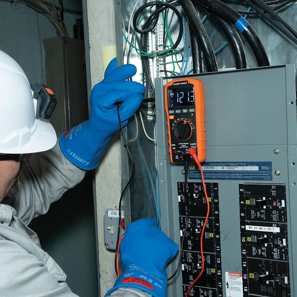
The image above illustrates an electrician using the MM720 to measure voltage within an electrical panel, demonstrating proper probe placement.
6.3.2 Current Measurement (AC/DC)
- Rotate the switch to 10A~ (AC Current), 10A- (DC Current), mA~ (AC mA), mA- (DC mA), µA~ (AC µA), or µA- (DC µA). Use the SEL button to toggle if needed.
- Connect the red lead to the appropriate current input (10A or mAµA) and the black lead to COM.
- Important: Connect the meter in series with the circuit to measure current. Never connect in parallel across a voltage source when in current mode.

The image above shows an electrician measuring current in an electrical panel, highlighting the series connection required for accurate current readings.
6.3.3 Resistance Measurement
- Rotate the switch to Ω.
- Connect the red lead to VΩHzCAPTemp and the black lead to COM.
- Ensure the circuit or component is de-energized before measuring resistance.
- Apply probes across the component.
6.3.4 Continuity Test
- Rotate the switch to the continuity/diode position (often indicated by a speaker icon). Press SEL if needed to select continuity.
- Connect the red lead to VΩHzCAPTemp and the black lead to COM.
- Apply probes across the circuit or component. A continuous beep indicates continuity.
6.3.5 Diode Test
- Rotate the switch to the continuity/diode position. Press SEL to select diode test (often indicated by a diode symbol).
- Connect the red lead to VΩHzCAPTemp and the black lead to COM.
- Apply probes across the diode. The display will show the forward voltage drop. Reverse the leads to check for open circuit.
6.3.6 Capacitance Measurement
- Rotate the switch to the capacitance position (often indicated by a capacitor symbol).
- Connect the red lead to VΩHzCAPTemp and the black lead to COM.
- Ensure the capacitor is fully discharged before testing.
- Apply probes across the capacitor terminals.
6.3.7 Frequency/Duty Cycle Measurement
- Rotate the switch to the Hz/% position.
- Connect the red lead to VΩHzCAPTemp and the black lead to COM.
- Apply probes to the signal source. Press SEL to toggle between frequency (Hz) and duty cycle (%).
6.3.8 Temperature Measurement
- Rotate the switch to the °F/°C position.
- Connect the thermocouple probe to the VΩHzCAPTemp and COM input jacks, observing polarity.
- Place the tip of the thermocouple on the object or area where temperature is to be measured. Press SEL to toggle between Fahrenheit and Celsius.
6.3.9 Low Impedance (LoZ) Mode
- Rotate the switch to the LoZ position.
- Connect the red lead to VΩHzCAPTemp and the black lead to COM.
- This mode applies a low impedance load across the circuit to drain ghost voltages, providing a more accurate reading of actual voltage.
7. Maintenance
7.1 Cleaning
Ensure the meter is turned off and disconnected from all circuits. Wipe the meter with a clean, dry, lint-free cloth. Do not use abrasive cleaners or solvents.
7.2 Battery Replacement
When the low battery indicator appears on the display, replace the batteries as described in Section 5.1. Failure to do so may result in inaccurate readings.
7.3 Fuse Replacement
If the current measurement functions cease to operate, the internal fuses may need replacement. Refer to the full user manual for detailed instructions on fuse replacement. This procedure typically requires opening the meter casing and should only be performed by qualified personnel.
7.4 Storage
When not in use for extended periods, remove the batteries to prevent leakage. Store the meter and its accessories in the provided carrying case in a cool, dry environment, away from direct sunlight and extreme temperatures.
8. Troubleshooting
If the meter is not functioning correctly, review the following common issues:
- No Display: Check if the batteries are correctly installed and have sufficient charge. Replace if necessary. Ensure the rotary switch is not in the OFF position.
- Inaccurate Readings: Verify that the correct function is selected for the measurement. Check test lead connections and ensure they are not damaged. Replace batteries if the low battery indicator is on.
- Current Measurement Not Working: Check the internal fuses. If blown, they need to be replaced (refer to Section 7.3). Ensure test leads are connected to the correct current input jacks.
- "OL" (Overload) Display: This indicates that the input value exceeds the selected range or the meter's maximum capability. Select a higher range if available, or ensure the measurement is within the meter's specifications.
For persistent issues, contact Klein Tools customer support.
9. Specifications
Below are the technical specifications for the Klein Tools MM720 Digital Multimeter.
| Specification | Value |
|---|---|
| Model Number | MM720 |
| AC/DC Voltage | Up to 1000V |
| AC/DC Current | Up to 10A |
| Resistance | Up to 60 MΩ |
| Temperature Range | -40°F to 1832°F (-40°C to 1000°C) |
| Capacitance | Yes |
| Frequency/Duty Cycle | Yes |
| Diode Test | Yes |
| Continuity | Yes |
| Low Impedance (LoZ) | Yes |
| True RMS | Yes |
| Auto-Ranging | Yes |
| Display | High visibility, reverse contrast LCD |
| Safety Rating | CAT IV 600V, CAT III 1000V |
| Ingress Protection (IP) Rating | IP42 |
| Drop Protection | 6.6-Foot (2 m) |
| Power Source | 2 x AAA Batteries |
| Product Dimensions | 10.63 x 5.87 x 3.73 inches |
| Item Weight | 12.17 ounces (345 Grams) |

The image above provides a comparison table detailing the features of the MM720 alongside other Klein Tools multimeter models, allowing for a quick overview of its capabilities relative to similar products.
10. Warranty and Support
Klein Tools products are manufactured to high standards of quality and durability. For specific warranty information, please refer to the warranty card included with your product or visit the official Klein Tools website.
For technical support, service, or replacement parts, please contact Klein Tools customer service. You can find more information and contact details by visiting the Klein Tools Store.