Introduction
Thank you for choosing the VBESTLIFE 100W Digital Amplifier Board. This versatile subwoofer amplifier module is designed for DIY speaker enthusiasts, offering powerful audio output with integrated preamplifier, bass crossover, and precise volume control. Its robust design and efficient operation make it an ideal component for enhancing your audio projects. Please read this manual thoroughly before installation and operation to ensure optimal performance and safety.
Safety Information
Always observe the following safety precautions to prevent injury or damage to the device:
- Ensure the power supply voltage is within the specified range (12-24V DC). Exceeding this range can damage the board.
- Do not connect the power supply with reverse polarity. This will cause immediate damage to the amplifier chip.
- Avoid short circuits on the output terminals. Always ensure speaker connections are correct before powering on.
- Keep the amplifier board away from water, moisture, and excessive heat.
- Handle the board with care to avoid damaging electronic components.
- Disconnect power before making any connections or disconnections.
Package Contents
Verify that all items are present in your package:
- 1 x Amplifier Board
- 1 x Adapter Cable
- 2 x Knob Cover
- 2 x Gasket
- 2 x Nut

Image: The amplifier board shown with its accompanying accessories, including the adapter cable, two knob covers, two gaskets, and two nuts.
Product Overview
The VBESTLIFE 100W Digital Amplifier Board is a compact yet powerful module designed for subwoofer applications. It integrates essential features for high-quality audio reproduction.

Image: A top-down view of the amplifier board, showcasing the heat sinks, capacitors, input/output terminals, and control knobs.
Key Features:
- Multi-Functional Design: Includes a preamplifier, bass crossover, and volume control for comprehensive audio management.
- High-Performance Chip: Utilizes a high-performance digital power amplifier chip (based on TI TPA3116D2) for clear and powerful sound output.
- Wide Operating Voltage: Supports a DC input voltage range of 12V to 24V, offering flexibility with various power sources.
- High Efficiency: Achieves up to 90% power efficiency, minimizing energy waste and heat generation.
- Robust Construction: Made with high-quality PCB materials and components to ensure stable and reliable performance.
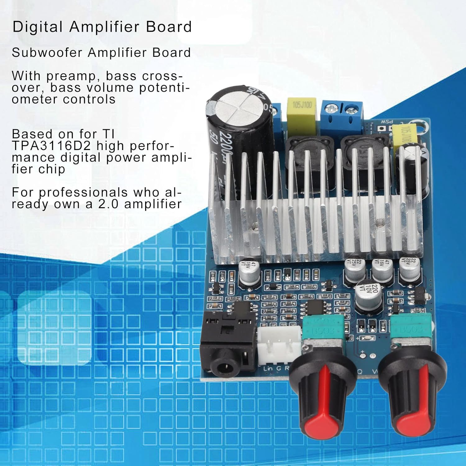
Image: The amplifier board with text overlays indicating its preamplifier, bass crossover, and volume potentiometer controls, and its high-performance digital amplifier chip.

Image: The amplifier board with text overlays emphasizing its 12-24V DC power supply compatibility, up to 90% efficiency, 100W bass channel output, and high-quality PCB materials for stable performance.
Setup
Follow these steps to set up your amplifier board:
- Prepare Components: Ensure you have the amplifier board, a compatible 12-24V DC power supply (e.g., switching power adapter, notebook power supply), and your subwoofer/speaker.
- Install Knobs: Attach the provided knob covers to the potentiometer shafts on the amplifier board. Secure them with the gaskets and nuts if necessary.
- Connect Subwoofer/Speaker: Locate the speaker output terminals on the amplifier board (typically labeled 'BASS' or with speaker symbols). Connect your subwoofer or speaker to these terminals. Ensure correct polarity (+ to + and - to -). The board supports subwoofer impedance from 2-8Ω.
- Connect Audio Input: Connect your audio source (e.g., preamplifier, audio player) to the audio input jack on the board. The sound input sensitivity is 500mV.
- Connect Power Supply: Connect your 12-24V DC power supply to the DC IN terminals on the board. Pay close attention to polarity. The board has a warning on the back: "Please check whether the circuit is properly connected and then plugged in the wrong line or line short circuit; may cause damage to the chip."
- Initial Power On: Once all connections are secure, you may power on your system. Start with the volume knob at its lowest setting.

Image: The underside of the amplifier board, showing the power input (DC 12-24V) and speaker output terminals, along with a warning about proper circuit connection to prevent chip damage.
Operating
Once the amplifier board is set up, you can begin operation:
- Power On/Off: The board typically powers on when the DC power supply is connected. Disconnect the power supply to turn it off.
- Volume Control: Use the main volume knob to adjust the overall output level of the subwoofer.
- Bass Crossover Control: The bass crossover knob allows you to adjust the upper frequency limit of the subwoofer output. This helps in blending the subwoofer's sound seamlessly with your main speakers. The output frequency range is 20Hz-180Hz.
- Output Power Considerations: The actual output power (up to 100W) is influenced by the power supply voltage, speaker impedance, and the input audio signal strength. Higher supply voltage generally supports higher output power. Speakers with lower impedance (e.g., 2Ω) are typically easier to drive to their maximum power.
Maintenance
To ensure the longevity and optimal performance of your amplifier board:
- Cleaning: Use a soft, dry cloth to gently wipe the board. Do not use liquid cleaners or solvents.
- Environment: Keep the board in a dry, well-ventilated area, away from direct sunlight, dust, and extreme temperatures.
- Handling: Avoid touching the electronic components directly, especially when powered on.
- Connections: Periodically check all connections to ensure they are secure and free from corrosion.
Troubleshooting
If you encounter issues with your amplifier board, refer to the following common problems and solutions:
| Problem | Possible Cause | Solution |
|---|---|---|
| No sound output |
|
|
| Distorted sound |
|
|
| Board not powering on |
|
|
| Bass crossover not effective |
|
|
Specifications
| Parameter | Value |
|---|---|
| Item Type | Amplifier Board |
| Material | PCB |
| Input Voltage | 12-24V DC |
| Output Power | 100W (Bass Channel) |
| Input Frequency | 20Hz-20KHz |
| Output Frequency (Bass) | 20Hz-180Hz |
| Sound Input Sensitivity | 500mV |
| Subwoofer Impedance | 2-8Ω |
| Efficiency | Up to 90% |
| Dimensions (Approx.) | 4.45 x 2.64 x 2.05 inches |
| Weight (Approx.) | 3.84 ounces |
Note: Components may vary slightly from batch to batch, but functional performance remains the same.
Warranty and Support
VBESTLIFE products are manufactured with high-quality standards. For any questions, technical support, or warranty claims, please contact your retailer or the VBESTLIFE customer service directly. Keep your purchase receipt as proof of purchase for warranty purposes.


