1. Introduction and Safety Instructions
This manual provides essential information for the safe and efficient operation, setup, and maintenance of your Arebos 500W Bench Drill Press. Please read and understand all instructions before using the machine.
General Safety Warnings
- Always wear appropriate personal protective equipment (PPE), including safety glasses, hearing protection, and gloves.
- Ensure the work area is clean, well-lit, and free from obstructions.
- Keep children and bystanders away from the operating machine.
- Securely fasten the drill press to a stable workbench to prevent tipping or movement during operation.
- Disconnect the power supply before making any adjustments, changing accessories, or performing maintenance.
- Never operate the drill press if any parts are damaged or missing.
- Always clamp the workpiece securely using the provided vise or other suitable clamping devices. Never hold the workpiece by hand.
- Select the correct drill speed for the material and drill bit size.
- Avoid loose clothing, jewelry, and long hair that could get caught in moving parts.

Figure 1: Overview of the Arebos 500W Bench Drill Press with the included workpiece vise.
2. Product Components
Familiarize yourself with the main components of your drill press:
- Motor Housing: Contains the 500W motor and speed adjustment mechanism.
- Power Switch: On/Off switch, often with a safety cover.
- Depth Stop: For setting precise drilling depth.
- Chuck: Holds the drill bit (13mm key chuck).
- Chuck Guard: Transparent guard for safety.
- Laser Guide: Projects crosshairs for accurate positioning.
- Feed Handles: Used to lower the chuck and drill bit.
- Column: Vertical support for the head and table.
- Workpiece Table: Adjustable height and tiltable platform for securing workpieces.
- Table Lock: Secures the workpiece table at the desired height.
- Base: Provides stability for the entire unit.
- Workpiece Vise: Included accessory for clamping materials.

Figure 2: Key features of the drill press, including the 500W motor, height-adjustable workpiece table, and 5 speed settings.
3. Setup and Assembly
Follow these steps for initial setup and assembly:
- Unpacking: Carefully remove all components from the packaging. Check for any damage during transit and ensure all parts are present according to the packing list.
- Base and Column Assembly: Securely attach the column to the base using the provided bolts and washers. Ensure it is firmly tightened.
- Head Assembly: Mount the drill head assembly onto the top of the column. Tighten the securing bolts.
- Workpiece Table Installation: Slide the workpiece table assembly onto the column. Adjust its height and secure it with the table lock handle.
- Chuck Installation: Clean the tapered shaft of the chuck and the spindle. Insert the chuck onto the spindle with a firm upward push to seat it properly.
- Vise Attachment: The included workpiece vise can be bolted to the workpiece table using the slots provided.
- Mounting the Machine: For stability and safety, bolt the drill press to a sturdy workbench using the holes in the base.

Figure 3: The drill press assembled with a drill bit in the chuck and the workpiece vise attached to the table.
4. Operating Instructions
4.1. Selecting Drill Speed
The drill press offers 5 variable speed settings (550 to 2500 RPM) suitable for various materials. To change the speed:
- Disconnect the machine from the power supply.
- Open the belt cover on top of the motor housing.
- Adjust the V-belt position on the pulleys according to the speed chart inside the cover.
- Ensure the belt is taut and close the cover before reconnecting power.
General Speed Guidelines:
- Lower Speeds: For larger drill bits, harder materials (metals), and plastics.
- Higher Speeds: For smaller drill bits, softer materials (wood), and plastics.

Figure 4: The belt drive system located under the top cover, used to adjust drilling speeds.
4.2. Installing a Drill Bit
- Ensure the machine is unplugged.
- Open the chuck jaws using the chuck key.
- Insert the drill bit into the chuck, ensuring it is centered and seated firmly.
- Tighten the chuck jaws securely with the chuck key. Remove the chuck key immediately after tightening.
4.3. Adjusting Workpiece Table
The workpiece table can be adjusted for height and angle:
- Height Adjustment: Loosen the table lock handle. Raise or lower the table to the desired height. Retighten the handle firmly.
- Angle Adjustment: Loosen the tilt bolt beneath the table. Tilt the table to the desired angle (up to 45 degrees). Retighten the bolt.

Figure 5: The workpiece table can be adjusted vertically along the column and tilted for angled drilling.
4.4. Using the Laser Guide
The integrated laser guide assists in precise drilling:
- Turn on the laser guide using its dedicated switch (if separate from main power).
- Position your workpiece so that the laser crosshairs align with your desired drilling point.
- Secure the workpiece firmly with the vise or clamps.

Figure 6: The laser guide projects a crosshair onto the workpiece, indicating the exact drilling point.
4.5. Drilling Operation
- Ensure the workpiece is securely clamped to the table.
- Adjust the depth stop if a specific drilling depth is required.
- Turn on the drill press.
- Slowly lower the drill bit into the workpiece using the feed handles. Apply steady, even pressure.
- Periodically retract the drill bit to clear chips, especially when drilling deep holes in metal.
- Once the desired depth is reached, retract the drill bit completely and turn off the machine.
- Wait for the spindle to stop completely before removing the workpiece.

Figure 7: A workpiece securely clamped in the vise during a drilling operation.
5. Maintenance
Regular maintenance ensures the longevity and safe operation of your drill press.
- Cleaning: After each use, clean the machine of dust, chips, and debris. Use a brush or vacuum cleaner. Do not use solvents that may damage painted surfaces or plastic parts.
- Lubrication: Periodically apply a light machine oil to moving parts such as the column, spindle, and feed mechanism to ensure smooth operation and prevent rust.
- Belt Inspection: Regularly check the V-belt for wear, cracks, or damage. Replace if necessary. Ensure proper tension.
- Chuck Maintenance: Keep the chuck jaws clean and free of debris. Apply a small amount of grease to the chuck key mechanism if it becomes stiff.
- Electrical Cord: Inspect the power cord for any signs of damage. Do not use the machine if the cord is frayed or damaged.
6. Troubleshooting
This section addresses common issues you might encounter:
| Problem | Possible Cause | Solution |
|---|---|---|
| Drill press does not start. | No power supply; faulty switch; motor overload. | Check power connection; inspect switch; allow motor to cool down. |
| Excessive vibration or noise. | Loose components; worn belt; unbalanced drill bit. | Check all fasteners; inspect and replace belt; ensure drill bit is properly seated and not bent. |
| Drill bit not cutting efficiently. | Dull drill bit; incorrect speed; insufficient pressure. | Sharpen or replace drill bit; adjust speed; apply steady pressure. |
| Drill bit wanders or breaks. | Workpiece not clamped securely; excessive feed pressure; incorrect speed. | Secure workpiece firmly; reduce feed pressure; adjust speed. |
| Laser guide not working. | Laser switch off; laser module faulty. | Ensure laser switch is on; contact service if still not working. |
If you encounter problems not listed here or if solutions do not resolve the issue, please contact customer support.
7. Technical Specifications
| Feature | Specification |
|---|---|
| Brand | Arebos |
| Model | B0B28K69ZB |
| Manufacturer | Canbolat Vertriebs GmbH |
| Power Source | Electric (corded) |
| Maximum Power | 500 Watt |
| Speed Settings | 5 (Variable) |
| Maximum Rotational Speed | 2500 RPM |
| Chuck Type | 13 mm Key Chuck |
| Special Features | Integrated Positioning Laser, Variable Speed |
| Product Dimensions (L x W x H) | 42 x 21 x 58 cm |
| Product Weight | 16.2 kg |
| First Available Date | May 25, 2022 |
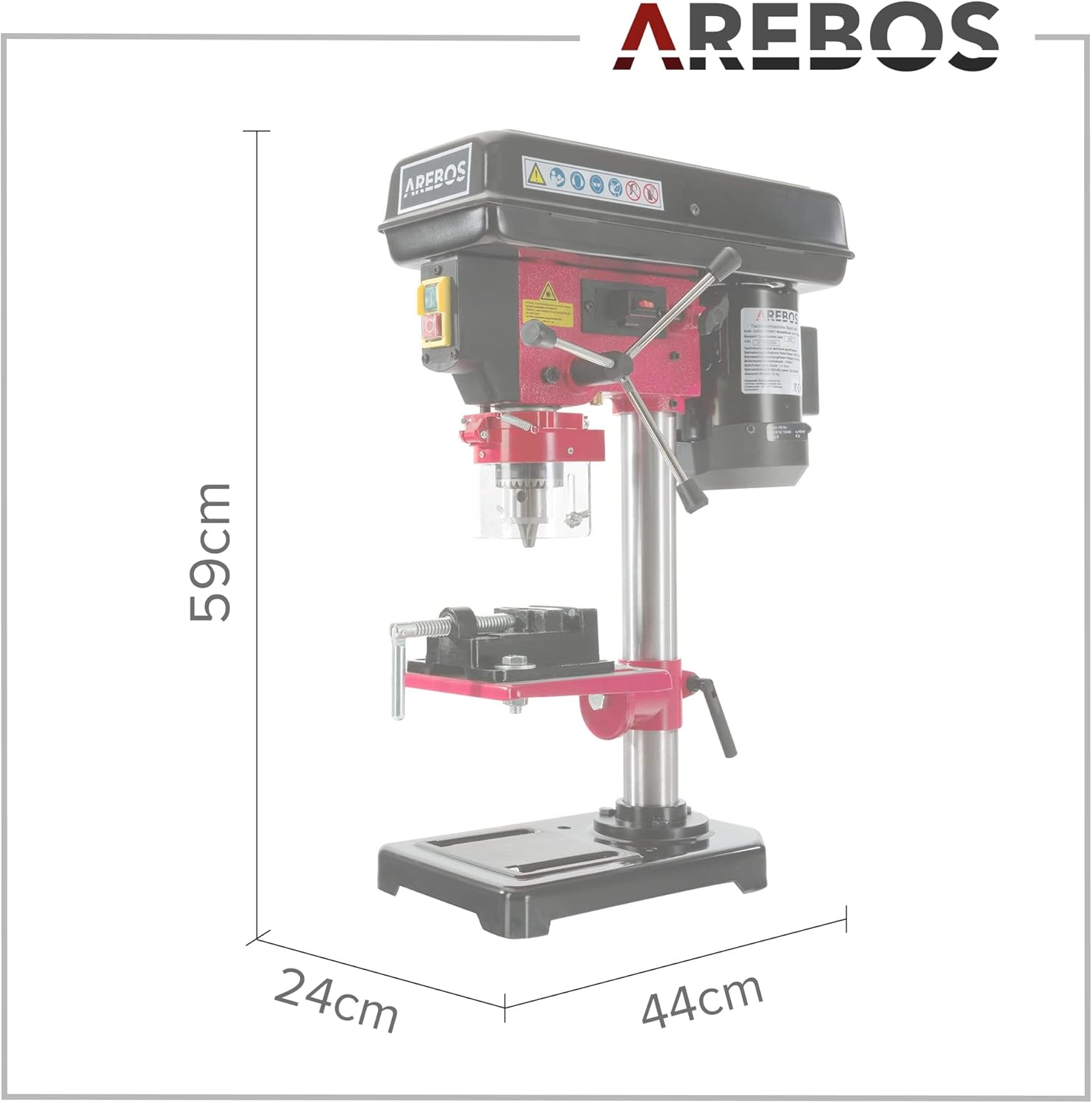
Figure 8: Dimensional overview of the Arebos Bench Drill Press.
8. Warranty and Customer Support
For warranty information, service, or technical support, please refer to the documentation included with your product or contact the manufacturer directly. The manufacturer is Canbolat Vertriebs GmbH.
Please retain your proof of purchase for any warranty claims.


