1. Product Overview
The DieseRC 2-Channel Wireless Relay Remote Control Switch is designed for remote control applications, operating at 433Mhz RF frequency. It features a receiver module and two keyfob transmitters, allowing for wireless control of various electrical devices. The receiver supports a DC input voltage range of 5V to 30V and has a maximum load capacity of 10A per channel.

Image 1.1: The DieseRC 2-Channel Wireless Relay Remote Control Switch receiver and two included keyfob remote controls.
2. Product Specifications
- Brand:
- DieseRC
- Model:
- 2 Channels Wireless Relay Remote Control Switch
- Input Voltage:
- DC 5V-30V
- Max Load Current:
- 10 Amps per channel
- RF Frequency:
- 433Mhz
- Output Style:
- Passive Output (Dry Contacts)
- Contact Type:
- Normally Open (NO), Common (COM), Normally Closed (NC)
- Operating Modes:
- Momentary, Toggle, Latched
- Transmitter Battery:
- A27 (Alkaline, included)
- Dimensions (Receiver):
- Approximately 95mm x 56mm x 24mm (3.7 x 2.2 x 0.9 inches)
- Weight:
- Approximately 5.6 ounces
3. Components and Features

Image 3.1: Detailed view of the receiver and remote control features.
- Receiver Board: Operates on DC 5V-30V. Includes an indicator light and a learning button for programming.
- Antenna: For receiving RF signals from the remote controls.
- Terminal Block: Features large screw ports for easy and secure wiring. Each of the two relays has Normally Open (NO), Common (COM), and Normally Closed (NC) pins.
- Remote Controls: Keyfob design with metal buttons, chrome bezel, and a sliding closure to protect buttons from accidental presses. Each remote has two buttons, typically labeled A and B.
- 433Mhz RF Technology: Provides stable and reliable wireless communication with high reception sensitivity.

Image 3.2: The receiver features large wiring ports for simplified installation.
4. Installation and Wiring
The receiver supports various cable types including single-strand hard wire, stranded hard wire, and stranded flexible wire. The large screw terminals facilitate easy and secure connections.

Image 4.1: Wiring compatibility and terminal details.
4.1 Terminal Definitions
- VIN: Positive power input (DC 5V-30V)
- GND: Negative power input
- NC1: Normally Closed for Relay 1
- COM1: Common for Relay 1
- NO1: Normally Open for Relay 1
- NC2: Normally Closed for Relay 2
- COM2: Common for Relay 2
- NO2: Normally Open for Relay 2
4.2 Wiring Diagrams
The receiver provides passive output (dry contacts), meaning it does not supply power to the connected device. You must provide external power to your device. The two relays are independent.
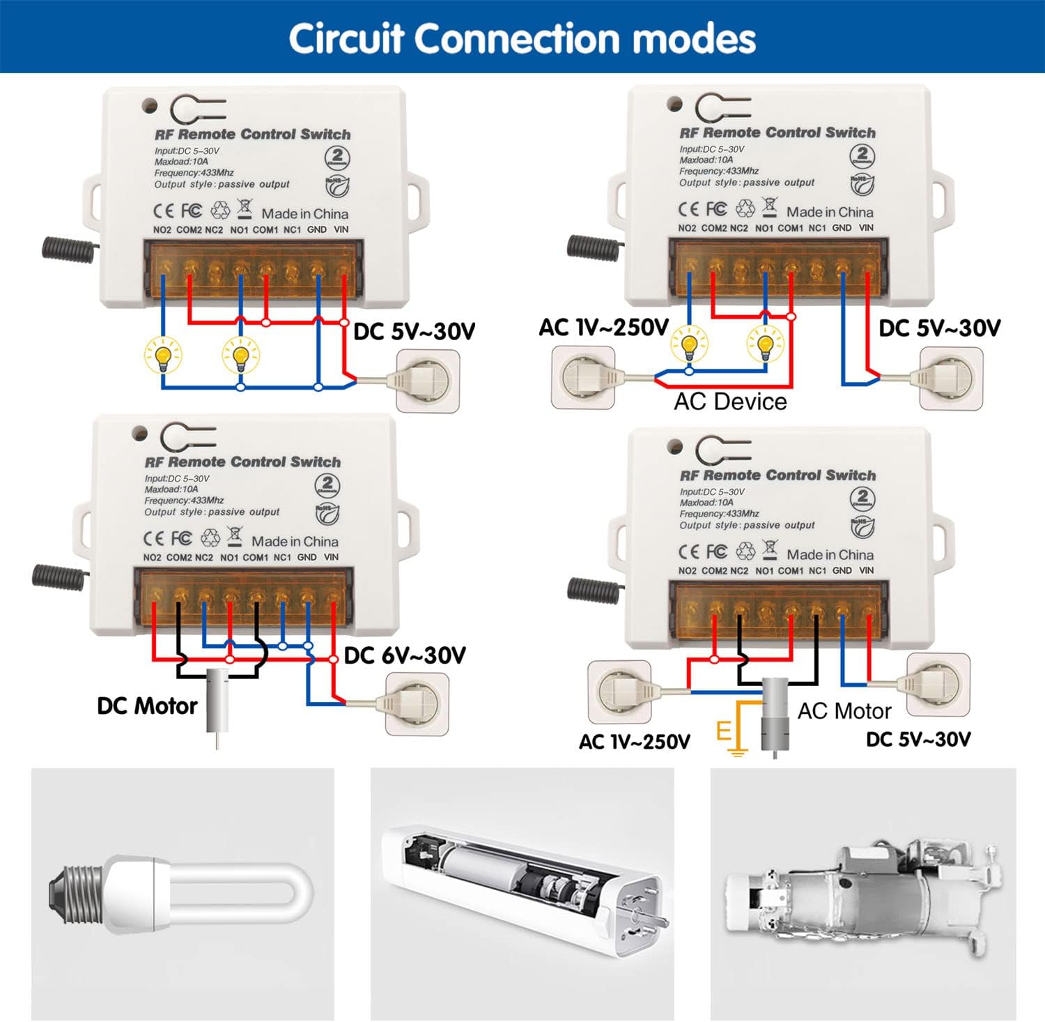
Image 4.2: Examples of various wiring configurations for DC lights, AC devices, DC motors, and AC motors.
General Wiring Steps:
- Connect the DC power supply (5V-30V) to the VIN (positive) and GND (negative) terminals of the receiver.
- Identify the appropriate relay contacts (NO, COM, NC) for your application.
- Connect your device's power circuit through the selected relay contacts. For example, to control a light, connect the power source to COM and the light to NO (for normally off, turning on when activated) or NC (for normally on, turning off when activated).
- Ensure all connections are secure and insulated.
5. Operating Modes
The receiver supports three operating modes: Momentary, Toggle, and Latched. The product is typically pre-programmed in Toggle mode.

Image 5.1: Visual explanation of Momentary, Toggle, and Latched operating modes.
5.1 Momentary Mode
In Momentary mode, the relay activates only while the remote button is pressed and held. Releasing the button deactivates the relay.
5.2 Toggle Mode
In Toggle mode, pressing a remote button once activates the relay, and it remains active. Pressing the same button again deactivates the relay.
5.3 Latched Mode
In Latched mode, pressing button 'A' activates Relay 1 and deactivates Relay 2 (if active). Pressing button 'B' activates Relay 2 and deactivates Relay 1 (if active). This mode typically requires a remote with at least two distinct buttons for independent control of two relays.
6. Programming Operating Modes (Learning Signal)
To change the operating mode or pair a new remote, follow these steps using the learning button on the receiver board.

Image 6.1: Programming steps for Momentary, Toggle, and Latched modes.
6.1 Programming Momentary Mode
- Press the learning button on the receiver 1 time. The indicator light will turn on.
- Press button 'A' on the remote control. The indicator light will flash once.
- Press button 'B' on the remote control. The indicator light will flash once, indicating successful programming.
6.2 Programming Toggle Mode
- Press the learning button on the receiver 2 times. The indicator light will turn on.
- Press button 'A' on the remote control. The indicator light will flash once.
- Press button 'B' on the remote control. The indicator light will flash once, indicating successful programming.
6.3 Programming Latched Mode
- Press the learning button on the receiver 3 times. The indicator light will turn on.
- Press button 'A' on the remote control. The indicator light will flash once.
- Press button 'B' on the remote control. The indicator light will flash once, indicating successful programming.
7. Reset Procedure (Clear All Paired Remotes)
To clear all previously paired remote controls from the receiver's memory, follow these steps:

Image 7.1: Resetting the receiver by pressing the learning button 8 times.
- Press the learning button on the receiver 8 times consecutively.
- The indicator light will flash several times and then turn off, indicating that all paired remotes have been cleared.
8. Troubleshooting
- Receiver not responding to remote:
- Ensure the receiver is powered correctly (DC 5V-30V).
- Check the remote control battery (A27).
- Verify the remote is paired to the receiver in the desired operating mode (see Section 6). If unsure, perform a reset (Section 7) and re-pair.
- Ensure there are no significant RF interferences or obstacles between the remote and receiver.
- Receiver not operating at 5V:
- While rated for 5V, some units may require a slightly higher voltage for reliable operation (e.g., 5.5V or 6V). If experiencing issues at 5V, try increasing the input voltage to 6V or higher within the specified 30V limit.
- Remote control stopped working after exposure to moisture:
- The remote controls are not waterproof. Exposure to water can cause damage or battery drain. Keep remotes dry. If exposed, open the remote, remove the battery, and allow it to dry completely before reinserting the battery. Replacement remotes may be necessary if damage persists.
- Relay clicks but device does not activate:
- Check wiring connections to the device (NO, COM, NC terminals).
- Ensure the device has its own power supply and that the relay contacts are correctly integrated into its circuit.
- Verify the device's power requirements do not exceed the relay's 10A maximum load.
9. Maintenance and Care
- Keep the receiver and remote controls in a dry environment.
- Avoid exposing the remote controls to moisture or direct water contact.
- Replace the remote control battery (A27) when the signal range decreases or the indicator light on the remote becomes dim.
- Ensure wiring connections remain secure over time.
10. Safety Information
- Always disconnect power before performing any wiring or maintenance on the receiver.
- Ensure the input voltage (DC 5V-30V) and load current (max 10A) are within the specified limits to prevent damage to the device or connected equipment.
- Do not attempt to modify the internal components of the receiver or remote controls.
- Keep out of reach of children.
11. Warranty and Support
For warranty information or technical support, please contact DieseRC customer service through your purchase platform or the official DieseRC website. Please have your product model and purchase details available.


