
1. Introduction
The UMLIFE STC-1000 is an all-purpose digital LED temperature controller designed for precise temperature management in various applications. It features both heating and cooling control capabilities with two relay outputs, making it suitable for maintaining desired temperatures in environments such as aquariums, incubators, refrigerators, and more. This manual provides detailed instructions for the safe and effective use of the STC-1000 temperature controller.
2. Safety Information
- Ensure the power supply voltage matches the controller's specified voltage (110V-220V AC).
- All wiring should be performed by a qualified professional to prevent electrical shock or damage to the device.
- Do not operate the device in environments with excessive humidity or corrosive gases.
- Keep the device away from water and direct sunlight.
- Disconnect power before performing any wiring or maintenance.
- The NTC sensor probe is waterproof and can be immersed in water, but the main controller unit is not.
3. Product Overview
The STC-1000 temperature controller features a clear digital display and intuitive buttons for setting parameters. It comes with a waterproof NTC sensor probe for accurate temperature measurement.
Front Panel Components

Figure 3.1: Front panel of the STC-1000 controller showing the digital display, power switch, setting button, and up/down buttons.
- Digital Display Window: Shows the current temperature and parameter settings.
- Power Switch (⏻): Turns the device on or off.
- UP Button (▲): Increases values or navigates menu options.
- DOWN Button (▼): Decreases values or navigates menu options.
- Setting Button (S): Enters parameter setting mode or confirms selections.
Dimensions and Sensor

Figure 3.2: Physical dimensions of the STC-1000 controller and the length of the NTC sensor probe.
The controller has a compact design for easy mounting. The NTC sensor probe is 1 meter long, allowing for flexible placement to monitor temperature.
4. Specifications
| Model | STC-1000 |
| Temperature Measurement Range | -50 to 99 ℃ |
| Temperature Control Range | -50 to 110 ℃ |
| Measurement Accuracy | ± 0.2 ℃ |
| Resolution | 0.1 ℃ |
| Control Accuracy | ± 0.1 ℃ |
| Sensor | NTC 10K L=1M waterproof probe |
| Power Supply | AC 110V-220V |
| Relay Contact Capacity | Cool (10A/220VAC), Heat (10A/220VAC) |
| Power Consumption | <3W |
| Ambient Temperature | 0℃ - 60℃ |
| Storage Temperature | -30℃ - 75℃ |
| Relative Humidity | 20-84% |
| Mounting Size | 71mm x 29mm |
| Product Dimensions | 75mm x 34.5mm x 85mm |
| Front Panel Size | 75mm x 34.5mm |
| Item Weight | 0.2 Kilograms (7 ounces) |
5. Installation
The STC-1000 controller is designed for panel mounting. Proper wiring is crucial for safe and correct operation.
Wiring Diagram

Figure 5.1: Top view of the STC-1000 wiring terminals.
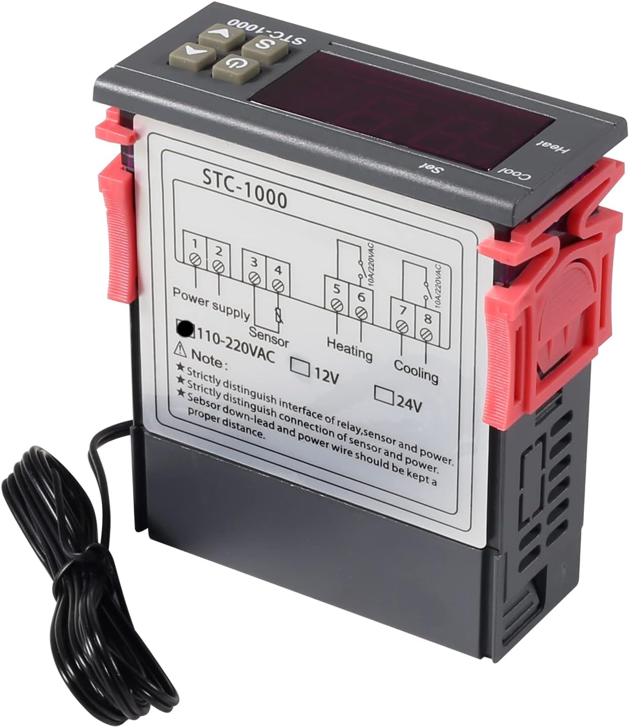
Figure 5.2: Side view of the STC-1000 controller with wiring terminals.
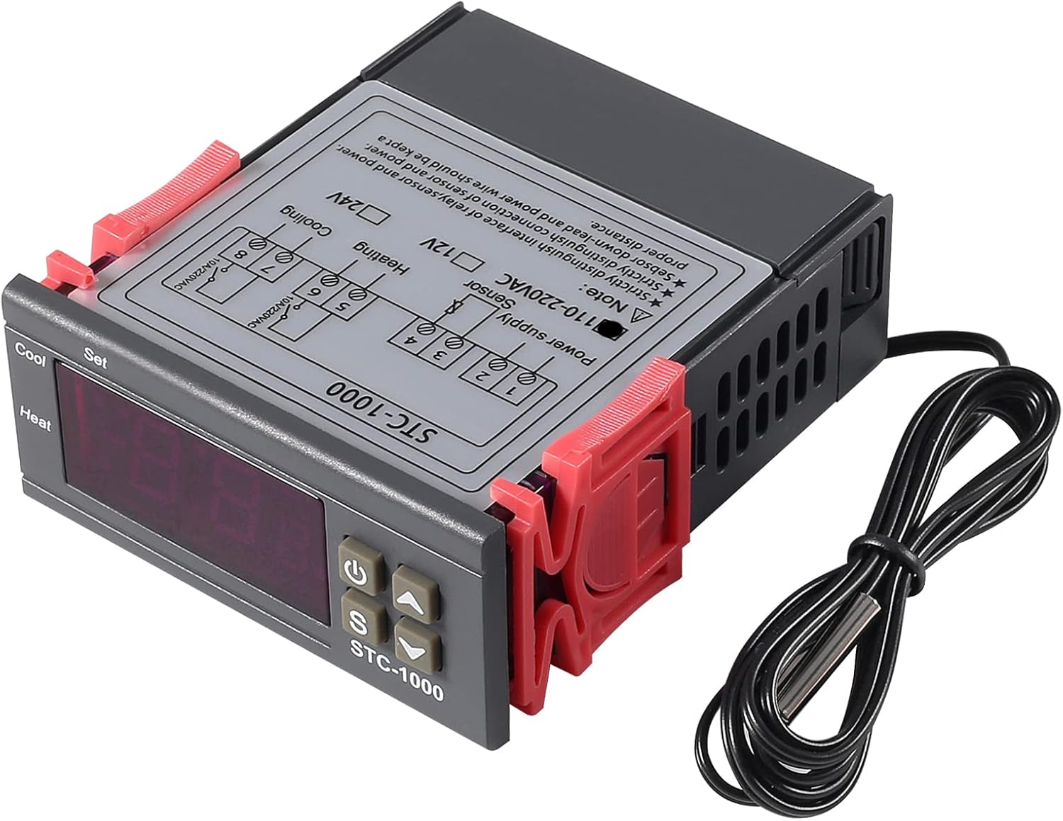
Figure 5.3: Angled view of the STC-1000 controller wiring.
Wiring Instructions:
- Power Supply (Terminals 1 & 2): Connect the AC 110V-220V power supply to terminals 1 and 2. Ensure correct polarity if applicable, though for AC, line and neutral can typically be interchanged.
- NTC Sensor (Terminals 3 & 4): Connect the NTC temperature sensor probe to terminals 3 and 4. The sensor is non-polarized.
- Heating Output (Terminals 5 & 6): Connect your heating device to terminals 5 and 6. This is a relay output, so ensure the heating device's power requirements do not exceed 10A/220VAC.
- Cooling Output (Terminals 7 & 8): Connect your cooling device to terminals 7 and 8. This is also a relay output, with a maximum capacity of 10A/220VAC.
Important Note: Strictly distinguish the interface of the relay, sensor, and power. Ensure the sensor down-lead and power wire are kept a proper distance to avoid interference.
6. Operation
The STC-1000 controller operates in two main modes: display mode and setting mode.
Display Mode
When powered on, the controller displays the current temperature measured by the NTC sensor.
Setting Parameters
To enter the parameter setting mode, press and hold the 'S' button for 3 seconds. The display will show 'F1'. Use the UP (▲) and DOWN (▼) buttons to navigate through the parameters (F1, F2, F3, F4). Press 'S' again to view or modify the value of the selected parameter. Use UP (▲) and DOWN (▼) to change the value, then press 'S' to confirm and save. To exit setting mode, press the power button or wait 10 seconds for it to automatically exit.
Parameter Functions:
- F1: Temperature Setting Value (Set Point)
This is the desired temperature you want to maintain. Range: -50℃ to 99℃. - F2: Differential Value (Hysteresis)
This sets the temperature difference between the set point and when the heating/cooling output activates. For example, if F1=25℃ and F2=2℃:- In cooling mode, cooling starts at 27℃ (25+2) and stops at 25℃.
- In heating mode, heating starts at 23℃ (25-2) and stops at 25℃.
- F3: Compressor Delay Time (Delay Start)
This parameter sets a delay before the compressor (cooling or heating device) starts after power-on or a cycle change. This protects the compressor from frequent starts. Range: 0 to 10 minutes. - F4: Temperature Calibration
Allows you to adjust the displayed temperature to match a known accurate thermometer. If the controller reads 25℃ but a reference thermometer reads 26℃, set F4 to +1.0℃. Range: -10℃ to 10℃.
Heating and Cooling Mode Selection
The controller automatically switches between heating and cooling based on the set point (F1) and differential (F2).
- If the current temperature is higher than (F1 + F2), the cooling relay activates.
- If the current temperature is lower than (F1 - F2), the heating relay activates.
7. Maintenance
- Regularly clean the controller's display and buttons with a soft, dry cloth.
- Ensure the sensor probe is clean and free from debris that could affect temperature readings.
- Periodically check all wiring connections to ensure they are secure.
- Avoid exposing the main unit to water or extreme temperatures.
8. Troubleshooting
| Problem | Possible Cause | Solution |
|---|---|---|
| Display shows 'HHH' or 'LLL' | Sensor error (open circuit or short circuit) or temperature exceeds range. | Check sensor wiring. Replace sensor if damaged. Ensure temperature is within -50℃ to 99℃. |
| Display shows 'EEE' | Sensor error or internal fault. | Check sensor wiring. If problem persists, the unit may be faulty. |
| Controller not responding to temperature changes | Incorrect F1/F2 settings, sensor not properly placed, or delay time (F3) is too long. | Verify F1 and F2 settings. Ensure sensor is accurately measuring the desired area. Check F3 setting. |
| Heating/Cooling device not turning on/off | Incorrect wiring, device faulty, or relay failure. | Recheck wiring connections for heating/cooling outputs. Test the connected device independently. |
9. Warranty and Support
UMLIFE products are manufactured to high-quality standards. For warranty information and technical support, please refer to the product packaging or contact your retailer. Keep your purchase receipt as proof of purchase.