1. Introduction
The GOLDEN BLUE DT-9205A is a versatile handheld digital multimeter designed for accurate measurement of various electrical parameters. It is an essential tool for electricians, hobbyists, and anyone working with electronics. This manual provides detailed instructions for safe and effective operation, maintenance, and troubleshooting of your DT-9205A multimeter.

Figure 1: GOLDEN BLUE DT-9205A Digital Multimeter.
2. Safety Information
Always observe the following safety precautions when using the multimeter to prevent personal injury or damage to the device:
- Do not exceed the maximum input values for any range.
- Never use the multimeter if the case is damaged or open.
- Ensure the test leads are properly connected and the function switch is set to the correct range before making any measurements.
- Be cautious when working with voltages above 30V AC RMS, 42V peak, or 60V DC, as they pose a shock hazard.
- Always disconnect the test leads from the circuit before changing the function switch position.
- Replace the battery when the low battery indicator appears to ensure accurate readings.
- Do not use the multimeter in wet environments or around explosive gas or dust.
3. Product Features
The DT-9205A Digital Multimeter offers a comprehensive set of features for various electrical measurements:
- Measures AC/DC voltage and current, resistance, frequency, diode, triode, continuity, and logic level.
- Clear LCD display for easy reading of measurement results.
- Integrated bracket on the back for convenient hands-free operation.
- Wide measuring range with high precision.
- Includes Sleep Mode to conserve battery life.
- Data Hold function to freeze the displayed reading.
- Maximum display count of 1999.

Figure 2: Overview of DT-9205A features and specifications.
4. Package Contents
Upon opening the package, please verify that all items listed below are present and in good condition:
- 1 x DT-9205A Digital Multimeter
- 1 x Pair of Test Leads (Red and Black)
- 1 x User Instruction Manual
Note: A 6F22 9V battery is required for operation and is NOT included in the package.
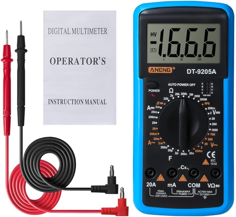
Figure 3: Contents of the DT-9205A package.
5. Setup
5.1 Battery Installation
- Ensure the multimeter is powered off.
- Locate the battery compartment cover on the back of the multimeter.
- Use a screwdriver to open the battery compartment.
- Insert a new 6F22 9V battery, observing the correct polarity (+/-).
- Replace the battery compartment cover and secure it with the screw.
5.2 Connecting Test Leads
The test leads are essential for making measurements. Connect them as follows:
- Insert the black test lead into the "COM" (Common) jack.
- For most voltage, resistance, and capacitance measurements, insert the red test lead into the "VΩHz" jack.
- For current measurements, insert the red test lead into the "mA" or "20A" jack, depending on the expected current range.

Figure 4: Key components and input jacks of the DT-9205A Multimeter.
6. Operating Instructions
Before taking any measurement, ensure the battery is installed and the test leads are correctly connected for the desired function.
6.1 Power On/Off
Press the POWER button to turn the multimeter on. The multimeter will automatically enter sleep mode after a period of inactivity to save battery. To turn it off manually, press the POWER button again.
6.2 Function Selection
Rotate the central Function Knob to select the desired measurement type (e.g., DC Voltage, AC Voltage, Resistance, Current, Diode, etc.). Ensure the knob points directly to the correct range for your measurement.
6.3 Specific Measurements
6.3.1 DC Voltage Measurement (V—)
- Connect the red test lead to the VΩHz jack and the black test lead to the COM jack.
- Set the function knob to the desired DC Voltage range (e.g., 200mV, 2V, 20V, 200V, 1000V).
- Connect the test leads in parallel across the DC voltage source.
- Read the voltage value on the LCD display.
6.3.2 AC Voltage Measurement (V~)
- Connect the red test lead to the VΩHz jack and the black test lead to the COM jack.
- Set the function knob to the desired AC Voltage range (e.g., 20V, 200V, 750V).
- Connect the test leads in parallel across the AC voltage source.
- Read the voltage value on the LCD display.

Figure 5: Example of AC voltage measurement using the DT-9205A.
6.3.3 DC Current Measurement (A—)
- Connect the black test lead to the COM jack.
- Connect the red test lead to the mA jack for currents up to 200mA, or to the 20A jack for currents up to 20A.
- Set the function knob to the desired DC Current range (e.g., 2mA, 20mA, 200mA, 20A).
- Connect the multimeter in series with the circuit to be measured.
- Read the current value on the LCD display.
6.3.4 AC Current Measurement (A~)
- Follow the same connection steps as DC Current measurement.
- Set the function knob to the desired AC Current range (e.g., 200mA, 20A).
- Connect the multimeter in series with the circuit.
- Read the current value on the LCD display.
6.3.5 Resistance Measurement (Ω)
- Connect the red test lead to the VΩHz jack and the black test lead to the COM jack.
- Set the function knob to the desired Resistance range (e.g., 200Ω, 2kΩ, 20kΩ, 200kΩ, 2MΩ, 20MΩ, 200MΩ).
- Ensure the circuit or component is de-energized before measuring resistance.
- Connect the test leads across the component to be measured.
- Read the resistance value on the LCD display.
6.3.6 Capacitance Measurement (F)
- Connect the red test lead to the VΩHz jack and the black test lead to the COM jack.
- Set the function knob to the desired Capacitance range (e.g., 2nF, 20nF, 200nF, 2µF, 20µF).
- Ensure the capacitor is fully discharged before measurement to prevent damage to the multimeter.
- Connect the test leads across the capacitor.
- Read the capacitance value on the LCD display.
6.3.7 Diode Test (→|→)
- Connect the red test lead to the VΩHz jack and the black test lead to the COM jack.
- Set the function knob to the Diode test position.
- Connect the red lead to the anode and the black lead to the cathode of the diode. A forward voltage drop will be displayed.
- Reverse the leads. An open circuit (OL) reading indicates a good diode.

Figure 6: Performing a diode measurement with the DT-9205A.
6.3.8 Continuity Test (♫)
- Connect the red test lead to the VΩHz jack and the black test lead to the COM jack.
- Set the function knob to the Continuity test position.
- Touch the test leads across the circuit or component. If continuity exists (resistance below a certain threshold), the buzzer will sound.
6.3.9 Transistor (hFE) Test
- Set the function knob to the hFE position.
- Insert the transistor's emitter, base, and collector leads into the corresponding E, B, C holes in the hFE socket, ensuring correct NPN or PNP type.
- Read the hFE value on the LCD display.

Figure 7: Illustrates various measurement functions including Triode, Resistance, and Diode tests.
7. Specifications
| Parameter | Range | Accuracy |
|---|---|---|
| DC Voltage | 200mV - 1000V | ±(0.5%+1dgt) |
| AC Voltage | 20V - 750V | ±(0.8%+3dgt) |
| DC Current | 20mA - 20A | ±(0.8%+1dgt) |
| AC Current | 200mA - 20A | ±(1.8%+3dgt) |
| Resistance | 200Ω - 200MΩ | ±(0.8%+1dgt) |
| Capacitance | 2nF - 20µF | ±(2.5%+3dgt) |
| Frequency | 2KHz - 20KHz | ±(1.5%+5dgt) |
| Diode Test | Yes | N/A |
| Triode Test | Yes | N/A |
| Continuity Test | Yes | N/A |
| Temperature Test | Yes | N/A |
| Logic Level Test | Yes | N/A |
| Maximum Display | 1999 | N/A |
| Power Supply | 6F22 9V Battery (Not included) | N/A |
| Dimensions | 194.5mm x 90.3mm x 30.3mm (7.65in x 3.55in x 1.19in) | N/A |
| Weight | 195g | N/A |
| Color | Blue | N/A |

Figure 8: Physical dimensions of the DT-9205A Multimeter.
8. Maintenance
8.1 Cleaning
To clean the multimeter, wipe the case with a damp cloth and a mild detergent. Do not use abrasives or solvents. Ensure the multimeter is completely dry before use.
8.2 Battery Replacement
When the low battery indicator appears on the display, replace the 9V battery as described in the "Battery Installation" section (5.1). Prompt battery replacement ensures accurate readings and proper operation.
8.3 Storage
If the multimeter is not used for an extended period, remove the battery to prevent leakage and damage to the device. Store the multimeter in a cool, dry place, away from direct sunlight and extreme temperatures.
9. Troubleshooting
| Problem | Possible Cause | Solution |
|---|---|---|
| No display or dim display | Low or dead battery; Multimeter not powered on. | Replace the 9V battery; Press the POWER button. |
| "OL" (Overload) displayed | Input value exceeds the selected range; Open circuit. | Select a higher range; Check for open circuit in the component/circuit. |
| Inaccurate readings | Low battery; Incorrect range selected; Poor test lead connection. | Replace battery; Select appropriate range; Ensure secure test lead connections. |
| No continuity beep | Open circuit; Resistance too high. | Check the circuit for breaks; Ensure resistance is within continuity threshold. |
10. Warranty and Support
For warranty information or technical support regarding your GOLDEN BLUE DT-9205A Digital Multimeter, please refer to the contact information provided on the product packaging or the official GOLDEN BLUE website. Keep your purchase receipt as proof of purchase for warranty claims.


