1. Introduction
Thank you for choosing the LoraTap Smart WiFi Roller Shutter Module. This module is designed to integrate your traditional roller shutter motor with smart home systems, allowing for convenient control via a smartphone app, voice commands, or your existing wall switch. Please read this manual carefully before installation and use to ensure proper operation and safety.
2. Product Features
- Compatibility: Works seamlessly with your existing traditional roller shutter wall switch.
- Partial Control: Innovative function to set motor running time for partial opening or closing of shutters.
- Remote Control: Connects directly to 2.4GHz Wi-Fi for remote control via the free Smart Life app (Android/iOS), no hub required.
- Scheduling: Program precise opening and closing times using the timer function in the Smart Life app.
- Voice Control: Compatible with Amazon Alexa and Google Home for hands-free operation.
- Group Function: Control multiple modules simultaneously for synchronized operation of several shutters.
- Device Sharing: Share control of the module with family members through the app.
- Motor Compatibility: Supports 4-wire motors (2 output, 1 neutral, 1 ground) and 5-wire motors with an integrated driver.
3. Package Contents

Image Description:
This image displays the items included in the product package. It shows the yellow LoraTap Roller Shutter Module, three colored cables for wiring, a small square of double-sided adhesive tape, a screwdriver, and a user guide booklet.
The package includes:
- LoraTap Smart WiFi Roller Shutter Module
- 3 x Cables for Wiring
- Double-sided Adhesive Tape
- Screwdriver
- User Guide
4. Specifications

Image Description:
This image illustrates the dimensions of the LoraTap Smart WiFi Roller Shutter Module. It shows the module with measurements indicating a length of 48mm, a width of 47mm, and a height of 22mm. A side view also confirms the 22mm thickness.
| Parameter | Value |
|---|---|
| Model No. | SC500W |
| Operating Mode | ON-OFF |
| Current Rating | 10 A |
| Operating Voltage | 100-250 Volts AC, 50/60Hz |
| Max. Load Power | 300W |
| Contact Type | Normally Closed |
| Connector Type | Terminal Block |
| Switch Type | Toggle |
| Terminal | Screw |
| Material | Acrylonitrile Butadiene Styrene (ABS) |
| Dimensions (L x W x H) | 48 x 47 x 22 millimeters |
5. Safety Information
WARNING: Risk of Electric Shock. Installation must be performed by a qualified electrician or a person with electrical knowledge. Always turn off power at the circuit breaker before installation, maintenance, or removal.
- Ensure the power supply is disconnected before handling any wiring.
- Verify that the module's specifications (voltage, current, load) are compatible with your motor and electrical system.
- Do not expose the device to moisture or extreme temperatures.
- Keep out of reach of children.
6. Installation
6.1 Pre-installation Checks
- Confirm your roller shutter motor is compatible (4-wire or 5-wire with integrated driver).
- Ensure your electrical box has sufficient space for the module (48x47x22mm).
- Turn off the main power supply to the circuit at the circuit breaker before proceeding.
6.2 Wiring Diagram

Image Description:
This image shows a detailed wiring diagram for the LoraTap Smart WiFi Roller Shutter Module. It illustrates connections for Input L (Live), Input N (Neutral), Output N (Neutral to motor), Output L (Live to motor), Output L1 (Motor Up), Output L2 (Motor Down), and connections for an external wall switch (S1, S2). It also shows the motor and earth wire (PE) connections.
Follow the diagram carefully for correct wiring:
- Connect the Live (L) and Neutral (N) wires from your power supply to the 'Input L' and 'Input N' terminals on the module.
- Connect the Neutral wire from your motor to the 'Output N' terminal on the module.
- Connect the Live wire from your motor to the 'Output L' terminal on the module.
- Connect the motor's 'Up' wire to the 'L1' terminal on the module.
- Connect the motor's 'Down' wire to the 'L2' terminal on the module.
- If using a traditional wall switch, connect the switch's 'Up' terminal to 'S1' and 'Down' terminal to 'S2' on the module. Ensure the switch is a momentary type or compatible with the module's input.
- Ensure all connections are secure and insulated.
6.3 Physical Installation

Image Description:
This image shows the LoraTap Smart WiFi Roller Shutter Module connected and installed within a wall box, behind a traditional double-rocker wall switch. The module's compact size allows it to fit discreetly behind the existing switch, with wires neatly connected to both the module and the switch.
After wiring, carefully place the module into the wall box, ensuring no wires are pinched. Secure the traditional wall switch back into place. Restore power at the circuit breaker.
7. Configuration & Pairing
7.1 Download the Smart Life App
Search for "Smart Life" in the Apple App Store or Google Play Store, or scan the QR code provided in the quick start guide (if applicable) to download and install the app.
7.2 Register and Log In
Open the Smart Life app, register a new account if you don't have one, and log in.
7.3 Add Device
- Ensure your phone is connected to a 2.4GHz Wi-Fi network.
- In the Smart Life app, tap the "+" icon in the top right corner to add a device.
- Select "Curtain Switch" or "Shutter Switch" from the device list (usually under "Electrician").
- Put the module into pairing mode: Press and hold the "Pairing Button" on the module for approximately 5 seconds until the indicator light flashes rapidly.
- Follow the on-screen instructions in the app to complete the pairing process. You will need to enter your Wi-Fi password.
- Once successfully added, you can rename the device for easier identification (e.g., "Living Room Shutter").
8. Operation
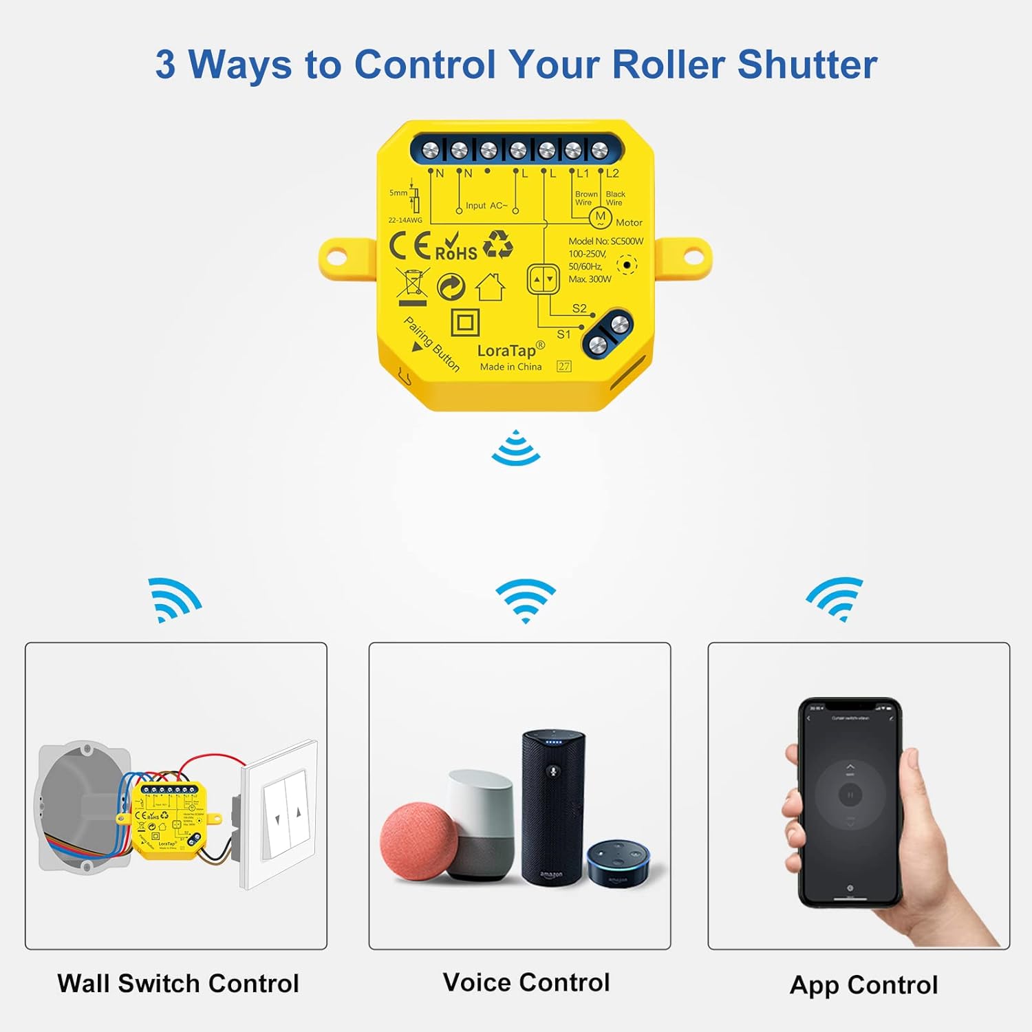
Image Description:
This image illustrates the three primary methods for controlling the LoraTap Smart WiFi Roller Shutter Module: Wall Switch Control (showing the module connected to a traditional wall switch), Voice Control (depicting Amazon Echo and Google Home devices), and App Control (showing a smartphone with the Smart Life app interface).
8.1 App Control
Once the module is paired, you can control your roller shutter from anywhere using the Smart Life app.
- Open/Close: Tap the respective buttons in the app interface to fully open or close the shutter.
- Partial Open/Close:

Image Description:
This image shows how to set the opening and closing time for the roller shutter within the Smart Life app. It displays three smartphone screens, each showing a different duration (1 second, 70 seconds, 120 seconds) being set, corresponding to different partial opening/closing positions of the roller shutter.
In the app settings for the device, you can set the motor's running time. This allows you to achieve a specific partial open or closed position. For example, if your shutter takes 120 seconds to fully close, setting the time to 60 seconds will close it halfway.
- Timers and Schedules:
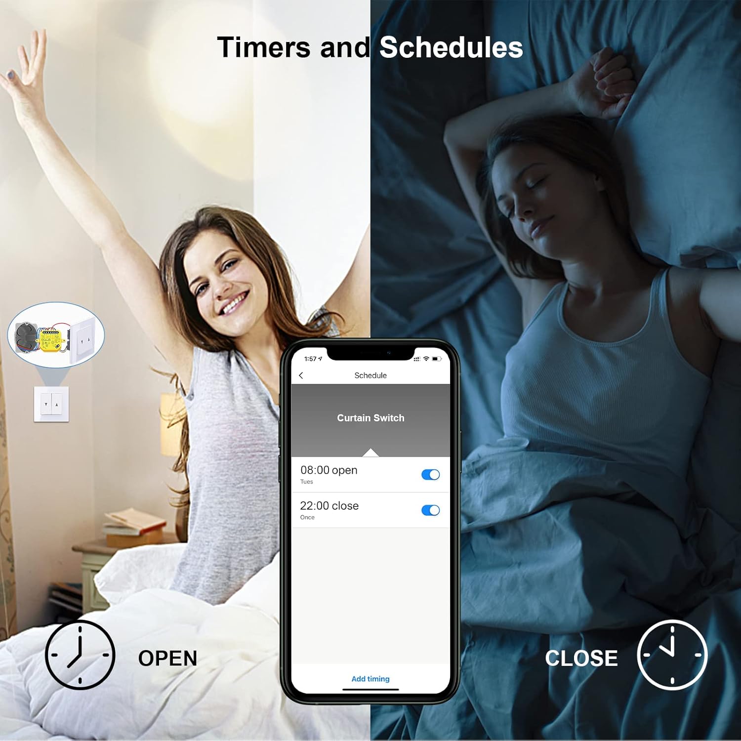
Image Description:
This image illustrates the timer and scheduling feature within the Smart Life app. It shows a smartphone screen with a 'Schedule' interface, where a user has set the shutter to open at 08:00 and close at 22:00. The background depicts a person waking up as the shutter opens and sleeping as it closes, emphasizing the convenience of automated schedules.
Access the 'Schedule' or 'Timer' function within the device settings in the app. You can set specific times for the shutter to open or close automatically on chosen days of the week.
- Group Function:
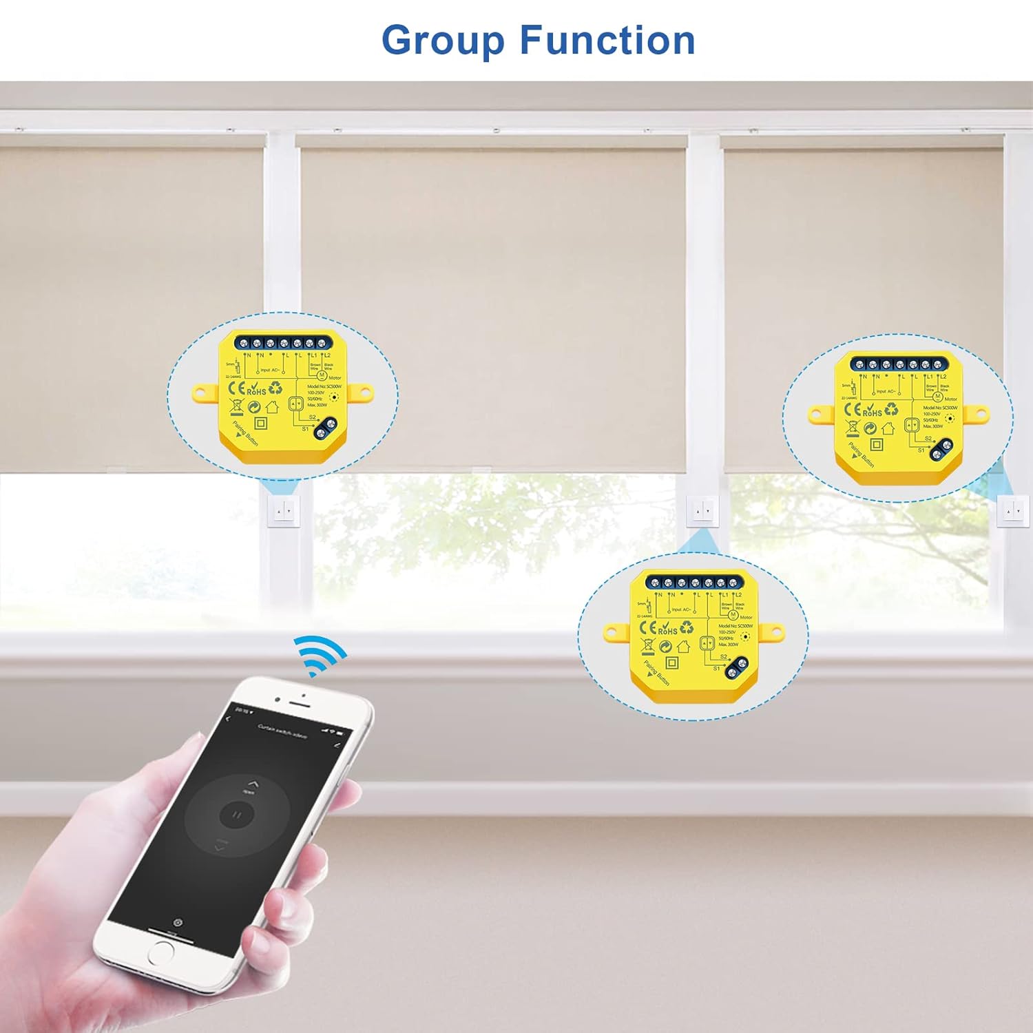
Image Description:
This image demonstrates the 'Group Function' feature, showing three LoraTap modules installed with three separate roller shutters. A hand holding a smartphone with the Smart Life app is shown, indicating that all three shutters can be controlled simultaneously as a group from a single command in the app.
If you have multiple LoraTap modules, you can create groups in the Smart Life app to control several shutters simultaneously with a single command.
- Device Sharing:
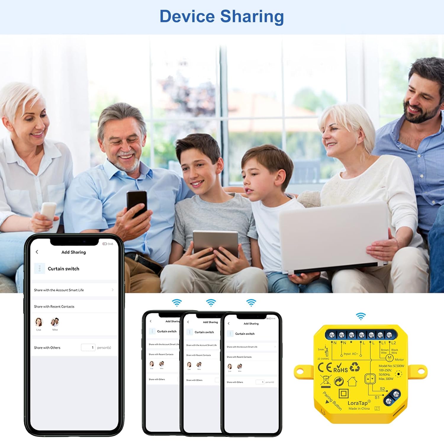
Image Description:
This image illustrates the 'Device Sharing' feature of the Smart Life app. It shows a family using smartphones and tablets, implying shared control of smart devices. The app interface on the phone shows options to 'Add Sharing' and manage shared contacts, allowing multiple users to control the LoraTap module.
Share control of your LoraTap module with family members by inviting them through the Smart Life app's sharing feature.
8.2 Voice Control
To enable voice control, link your Smart Life account with Amazon Alexa or Google Home through their respective apps.
- For Amazon Alexa:
- Open the Alexa app, go to 'Skills & Games', search for 'Smart Life', and enable the skill.
- Link your Smart Life account.
- Discover devices.
- You can now use commands like: "Alexa, open [Device Name]", "Alexa, close [Device Name]", "Alexa, set [Device Name] to 50%" (if partial control is supported by the voice assistant).
- For Google Home:
- Open the Google Home app, tap 'Add' > 'Set up device' > 'Works with Google'.
- Search for 'Smart Life', link your account.
- Assign devices to rooms.
- You can now use commands like: "Hey Google, open [Device Name]", "Hey Google, close [Device Name]".
8.3 Traditional Wall Switch Control
The LoraTap module is designed to work in conjunction with your existing traditional wall switch. You can continue to use the physical switch to control your roller shutter (open, stop, close) even after installing the smart module.
9. Maintenance
The LoraTap Smart WiFi Roller Shutter Module requires minimal maintenance. Follow these guidelines:
- Keep the module and surrounding area clean and free from dust.
- Do not attempt to open or repair the module yourself. Refer to qualified personnel for any issues.
- Ensure the module is not exposed to water or excessive humidity.
10. Troubleshooting
- Module not responding:
- Check if the power supply to the module is on.
- Verify Wi-Fi connectivity. Ensure the module is within range of your 2.4GHz Wi-Fi router.
- Restart the module by turning off and on the power at the circuit breaker.
- Try re-pairing the module with the Smart Life app.
- Cannot connect to Wi-Fi:
- Ensure your Wi-Fi network is 2.4GHz. The module does not support 5GHz networks.
- Check your Wi-Fi password for correctness.
- Move the module closer to your Wi-Fi router during pairing.
- Ensure your router is not using a hidden SSID or MAC filtering that would block new devices.
- Shutter not moving or moving incorrectly:
- Verify all wiring connections are secure and correct according to the diagram.
- Ensure the motor is functioning correctly when controlled by the traditional switch (if applicable).
- Check the motor's running time setting in the app for partial control issues.
- Voice control not working:
- Ensure your Smart Life account is correctly linked to Alexa/Google Home.
- Check the device name in the Smart Life app and use that exact name in your voice commands.
- Try rediscovering devices in the Alexa/Google Home app.
11. Warranty & Support
LoraTap products come with a 2-year warranty from the date of purchase. This warranty covers defects in materials and workmanship under normal use.
The warranty does not cover:
- Damage caused by improper installation or wiring.
- Damage caused by unauthorized modification or repair.
- Damage caused by misuse, abuse, or neglect.
- Damage caused by natural disasters or acts of God.
For technical support, warranty claims, or further assistance, please contact LoraTap customer service through the contact information provided on their official website or through your purchase platform. Please have your model number (SC500W) and proof of purchase ready.


