1. Introduction
This instruction manual provides comprehensive guidance for the safe and efficient assembly, installation, operation, and maintenance of your Extralink Wall-Mount Network Cabinet, Model EX.14435. Please read this manual thoroughly before proceeding with any installation or operation to ensure proper usage and to prevent damage to the product or connected equipment.
The Extralink network cabinet is designed to securely house various network devices such as switches, UPS systems, and servers, providing an organized and protected environment for your IT infrastructure.
2. Safety Instructions
WARNING: Failure to follow these safety instructions may result in injury, equipment damage, or voiding of the warranty.
- Always ensure the cabinet is securely mounted to a structurally sound wall capable of supporting the cabinet's weight plus the weight of all installed equipment.
- Do not overload the cabinet beyond its specified weight capacity.
- Ensure proper grounding for all electrical equipment installed within the cabinet.
- Keep all ventilation openings clear to prevent overheating.
- Use appropriate personal protective equipment (PPE) during assembly and installation, such as gloves and safety glasses.
- Keep children and unauthorized personnel away from the installation area.
3. Package Contents
Verify that all components listed below are present and undamaged before beginning assembly. If any parts are missing or damaged, contact your supplier immediately.
- Cabinet frame components (top, bottom, side panels, front door)
- Mounting rails (19-inch standard)
- Assembly hardware (screws, nuts, washers)
- Keys for side panels and front door
- Wall mounting hardware (check suitability for your wall type)
- Instruction Manual (this document)
4. Setup and Assembly
The Extralink network cabinet features a self-assembly design for ease of transport and reduced shipping costs. Follow these steps for proper assembly and wall mounting.
4.1. Cabinet Assembly
- Unpack all components and lay them out on a clean, flat surface.
- Assemble the main frame by connecting the top and bottom panels to the rear frame section using the provided hardware. Ensure all connections are secure.
- Install the 19-inch mounting rails inside the cabinet frame. Adjust their depth as needed for your equipment.
- Attach the front door to the main frame using the hinge mechanisms.
- Install the side panels. These panels feature snap-on buttons for easy removal and are secured with included locks and keys.
4.2. Wall Mounting
Before mounting, ensure the chosen wall can support the total weight of the cabinet and its contents.
- Determine the desired mounting location and height.
- Mark the drilling points on the wall using the cabinet's mounting holes as a template.
- Drill pilot holes appropriate for your wall type and mounting hardware.
- Securely attach the cabinet to the wall using suitable anchors and screws. It is recommended to have at least two people for this step due to the cabinet's size and weight.
4.3. Cable Management and Ventilation
- The cabinet features cable entry holes on both the top cover and the bottom panel for organized cable routing.
- The cabinet ceiling includes two designated spaces for installing cooling fans (fans not included) to enhance airflow and prevent equipment overheating.
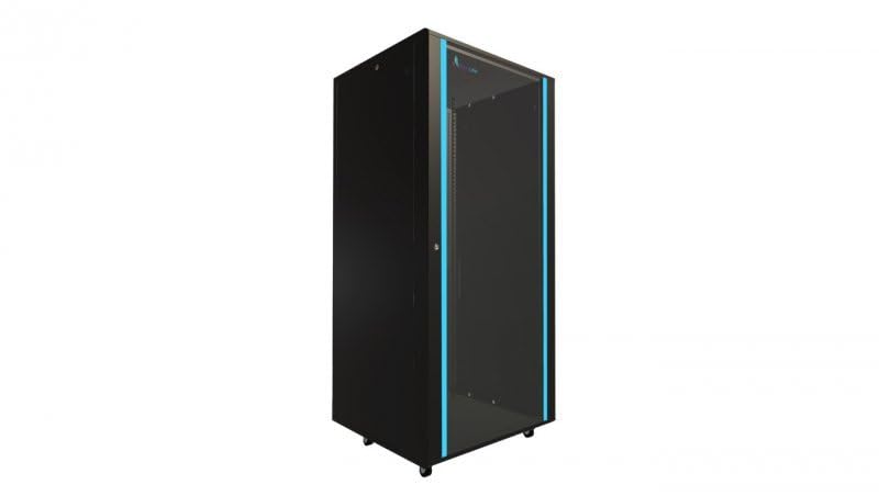
Figure 1: Assembled Extralink Wall-Mount Network Cabinet EX.14435. This image shows the front view of the black network cabinet, highlighting its robust construction and front door.
5. Operating Instructions
Once the cabinet is securely mounted, you can begin installing your network equipment.
- Unlock and open the front door and/or remove the side panels for easier access.
- Mount your 19-inch standard equipment (e.g., switches, patch panels, servers, UPS) onto the adjustable mounting rails using appropriate rack screws (not included).
- Route all necessary cables through the designated cable entry holes. Utilize cable ties or other management accessories to keep cables organized and prevent obstruction of airflow.
- If installing cooling fans, ensure they are properly wired and functioning to maintain optimal temperatures inside the cabinet.
- Close and lock the front door and side panels to secure your equipment.
6. Maintenance
Regular maintenance ensures the longevity and optimal performance of your network cabinet.
- Cleaning: Periodically wipe down the exterior surfaces with a soft, damp cloth. Avoid abrasive cleaners or solvents.
- Inspection: Annually inspect all mounting hardware and cabinet connections for tightness and signs of wear. Re-tighten as necessary.
- Ventilation: Ensure that all ventilation openings remain clear of dust and debris. Clean fan filters (if installed) regularly.
- Locks: Lubricate locks periodically to ensure smooth operation.
7. Troubleshooting
This section addresses common issues you might encounter.
- Issue: Equipment inside the cabinet is overheating.
Solution: Verify that cooling fans are installed and operating correctly. Ensure cable routing does not obstruct airflow. Check that the cabinet's ventilation openings are not blocked. - Issue: Cabinet feels unstable after mounting.
Solution: Re-check all wall mounting hardware and ensure it is securely fastened to a suitable wall structure. Confirm that the cabinet is not overloaded beyond its weight capacity. - Issue: Side panels or front door are difficult to open/close.
Solution: Check for any obstructions. Lubricate hinges and locks if necessary. Ensure the cabinet frame is square and not warped.
8. Specifications
| Feature | Specification |
|---|---|
| Brand | EXTRALINK |
| Model Number | EX.14435 |
| Color | Black (800 x 800 mm) |
| Material | Alloy Steel |
| Mounting Type | Wall Mount |
| Standard | 19-inch welded frame |
| Compatible Devices | Modem, Router, Switch, UPS, Server |
| Special Features | Removable side panels with locks, Self-assembly design, Fan mounting provisions, Cable entry holes |
9. Warranty and Support
This Extralink product is covered by a manufacturer's warranty against defects in materials and workmanship. For specific warranty terms and conditions, please refer to the documentation provided at the time of purchase or contact your retailer.
For technical support, troubleshooting assistance, or to inquire about replacement parts, please contact Extralink customer service through their official website or the contact information provided by your retailer.


