1. Introduction
This manual provides detailed instructions for the installation, operation, and maintenance of your GAMEMAX Master M905 ATX Full Tower Computer Case. Please read this manual thoroughly before beginning assembly to ensure proper setup and safe usage. This computer case is designed to accommodate ATX motherboards and offers ample space for high-performance components and advanced cooling solutions.
2. Safety Information
- Always disconnect the power supply from the wall outlet before installing or removing any components to prevent electrical shock.
- Handle internal components with care. Avoid touching circuit boards directly; hold them by their edges.
- Wear an anti-static wrist strap when handling sensitive electronic components to prevent electrostatic discharge (ESD) damage.
- Keep small parts and screws away from children.
- Ensure proper ventilation around the computer case to prevent overheating.
3. Package Contents
Verify that all items listed below are present in your package:
- GAMEMAX Master M905 ATX Full Tower Computer Case
- Accessory Box (containing screws, standoffs, cable ties, and user manual)
- Pre-installed cooling fans (quantity may vary by model variant)
4. Component Identification
Familiarize yourself with the various parts of the GAMEMAX Master M905 case.

Figure 4.1: Front-left view of the GAMEMAX Master M905 case, showcasing the tempered glass side panel and the front mesh panel with two illuminated blue fans. The top panel features front I/O ports.

Figure 4.2: Top-front perspective of the case, showing the top ventilation grille and the front I/O panel which includes USB 2.0 and USB 3.0 ports, audio jacks, and power/reset buttons.
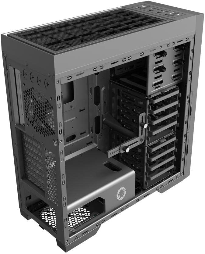
Figure 4.3: Internal view of the case, illustrating the spacious interior with multiple drive bays, the motherboard mounting area, and the dedicated power supply shroud at the bottom.
5. Installation Guide
5.1. Preparing the Case
- Remove Side Panels: Locate the thumbscrews on the rear of the case. Unscrew them and carefully slide off the tempered glass side panel and the solid steel side panel. Set them aside on a soft, non-abrasive surface.
- Accessory Box: Locate the accessory box inside the case, usually secured in a drive bay. This box contains all necessary screws, standoffs, and cable ties for installation.
5.2. Motherboard Installation
- Install Standoffs: Identify the correct standoff locations for your ATX motherboard. The Master M905 typically has pre-installed standoffs for ATX. If not, install them using the provided tool.
- Install I/O Shield: Snap your motherboard's I/O shield into the opening at the rear of the case from the inside. Ensure it is securely seated.
- Mount Motherboard: Carefully align your motherboard with the standoffs and the I/O shield. Gently lower the motherboard into place.
- Secure Motherboard: Use the provided motherboard screws to secure the motherboard to the standoffs. Do not overtighten.
5.3. Power Supply Unit (PSU) Installation
- Position PSU: The Master M905 supports bottom-mounted PSUs. Slide your PSU into the designated compartment at the bottom rear of the case, ensuring the fan faces downwards (if the case has a bottom vent) or upwards.
- Secure PSU: Align the PSU with the screw holes at the rear of the case. Secure it with the provided PSU screws.
5.4. Storage Drive Installation (HDD/SSD)
The case supports various drive configurations. Refer to the internal layout for specific bay types.
- 3.5" HDDs: Typically installed in tool-less drive cages or trays. Slide the HDD into a tray and secure it with clips or screws.
- 2.5" SSDs: Can be mounted on dedicated SSD brackets behind the motherboard tray or in 3.5" drive trays using adapter screws.
5.5. Expansion Card Installation (PCIe)
- Remove Slot Covers: Unscrew or remove the necessary PCIe slot covers from the rear of the case corresponding to your motherboard's PCIe slots.
- Install Card: Carefully insert your expansion card (e.g., graphics card) into the appropriate PCIe slot on the motherboard until it clicks into place.
- Secure Card: Secure the expansion card to the case with the provided screws.
5.6. Front Panel Connector Installation
Connect the front panel cables from the case to the corresponding headers on your motherboard. Consult your motherboard manual for exact header locations.
- USB 2.0/3.0: Connect the USB cables to the motherboard's USB headers.
- Audio: Connect the HD Audio cable to the motherboard's audio header.
- Power/Reset/LEDs: Connect the small individual cables (Power SW, Reset SW, HDD LED, Power LED) to the front panel header pins on your motherboard. Pay close attention to polarity for LEDs.
5.7. Cable Management
Utilize the cable routing cutouts and tie-down points behind the motherboard tray to organize cables. This improves airflow and aesthetics.
6. Operation
6.1. Powering On
Once all components are installed and cables are connected, replace the side panels. Connect your monitor, keyboard, mouse, and power cable to the PSU. Press the power button on the front panel to start your system.
6.2. Front I/O Ports
The front panel provides convenient access to:
- USB 2.0 Ports: For connecting peripherals like keyboards, mice, and older USB devices.
- USB 3.0 Ports: For high-speed data transfer with compatible devices.
- Audio Jacks: For connecting headphones and microphones.
- Power Button: To turn the system on/off.
- Reset Button: To restart the system.
7. Maintenance
7.1. Cleaning
Regular cleaning helps maintain optimal performance and extends the lifespan of your components.
- Exterior: Wipe the exterior surfaces with a soft, damp cloth. Avoid harsh chemicals.
- Interior: Use compressed air to remove dust from fans, heatsinks, and other components. Perform this outdoors or in a well-ventilated area.
7.2. Dust Filter Maintenance
The Master M905 case is equipped with dust filters to prevent dust buildup. Regularly clean these filters:
- Locate and remove the dust filters (e.g., front, top, bottom PSU intake).
- Rinse them under running water or use a soft brush to remove accumulated dust.
- Ensure filters are completely dry before re-installing them.
8. Troubleshooting
If you encounter issues, consider the following basic troubleshooting steps:
- System not powering on: Check all power connections, including the PSU to the wall, the 24-pin ATX connector, and the 8-pin CPU power connector to the motherboard. Ensure the front panel power switch cable is correctly connected to the motherboard.
- Fans not spinning: Verify that all fan cables are securely connected to the motherboard fan headers or a fan controller.
- USB ports not working: Ensure the front panel USB cables are correctly connected to the motherboard's USB headers.
- No display output: Confirm that your graphics card is properly seated in its PCIe slot and that all necessary power cables are connected to it. Ensure your monitor cable is connected to the graphics card, not the motherboard's integrated graphics ports (unless you are using integrated graphics).
9. Specifications
| Feature | Specification |
|---|---|
| Brand | GAMEMAX |
| Model | Master M905 |
| Case Type | Full Tower |
| Motherboard Compatibility | ATX |
| Material | Steel, Tempered Glass |
| Color | Black |
| Product Dimensions (LxWxH) | 23.5 x 22.95 x 11.26 inches |
| Front I/O Ports | 2x USB 2.0, 2x USB 3.0, Audio In/Out |
| Expansion Slots | 8 |
| Cooling Method | Air, Water |
| Power Supply Mounting Type | Tower (Bottom-mounted) |
10. Warranty and Support
For warranty information and technical support, please refer to the official GAMEMAX website or contact your local retailer. Keep your proof of purchase for warranty claims.


