
1. Introduction
The GODOX TT520Ⅱ is a versatile on-camera flash electronic speedlite designed for various DSLR cameras, including Canon, Nikon, Pentax, and Olympus. It features a high guide number, multiple flash modes (M, S1, S2), and a fast recycle time, making it suitable for diverse photographic environments. This manual provides detailed instructions for the proper setup, operation, maintenance, and troubleshooting of your TT520Ⅱ flash unit.

Figure 1.1: GODOX TT520Ⅱ Flash Speedlite with AT-16 Wireless Trigger.
This image displays the GODOX TT520Ⅱ flash unit alongside its AT-16 2.4G wireless trigger. The flash unit is black with a rectangular head and a red panel, while the trigger is a smaller black rectangular device with a single button.
2. Safety Information
- Do not disassemble or modify the flash unit. This can lead to electric shock or damage.
- Keep the device away from water and moisture to prevent short circuits.
- Avoid direct eye exposure to the flash, especially at close range, as it can cause temporary vision impairment.
- Use only compatible batteries and dispose of them properly.
- Do not operate the flash in environments with flammable gases or liquids.
- Ensure the flash is securely mounted to prevent accidental drops.
3. Package Contents
Please check the package contents upon opening to ensure all items are present:
- GODOX TT520Ⅱ Flash Speedlite
- AT-16 2.4G Wireless Trigger Transmitter
- Mini Stand
- Soft Box (typically included with some kits)
- Reflector/Diffuser (built-in or separate)
- User Manual (this document)
4. Product Overview
Familiarize yourself with the components of the GODOX TT520Ⅱ flash unit and its wireless trigger.

Figure 4.1: Labeled components of the GODOX TT520Ⅱ Flash Speedlite.
This diagram illustrates the various parts of the flash unit, including the Mode Selection Button (M, S1, S2), Output Level Indicator, Flash Power Level Button, Motion Selection, Charging Indicator, Power Switch, Battery Compartment, Test Button, Built-in Panel, Flash Head, Optic Control Sensor, Hot Shoe, Lock Ring, Mini Stand, Dedicated Hot Shoe Contact, Socket Cover, PC Sync Socket, and Charging Socket.
4.1. Flash Unit Features
- Flash Head: Rotates horizontally 270° and vertically 90° for bounce flash.
- Control Panel: Buttons for mode selection (M, S1, S2) and power output adjustment.
- Hot Shoe: Standard hot shoe for mounting on DSLR cameras.
- Optic Control Sensor: For S1/S2 slave modes.
- PC Sync Socket: For wired synchronization with cameras or triggers.
- Battery Compartment: Houses the power source (typically AA batteries).

Figure 4.2: Horizontal and vertical rotation capabilities of the flash head.
This image demonstrates the flexibility of the flash head, showing its ability to rotate 270 degrees horizontally and 90 degrees vertically, allowing for various bounce flash angles.
4.2. Wireless Trigger (AT-16) Features
- 2.4G Wireless Technology: Provides reliable remote triggering.
- Single Button Operation: Simple and intuitive to use.
- Hot Shoe Mount: Attaches to the camera's hot shoe.
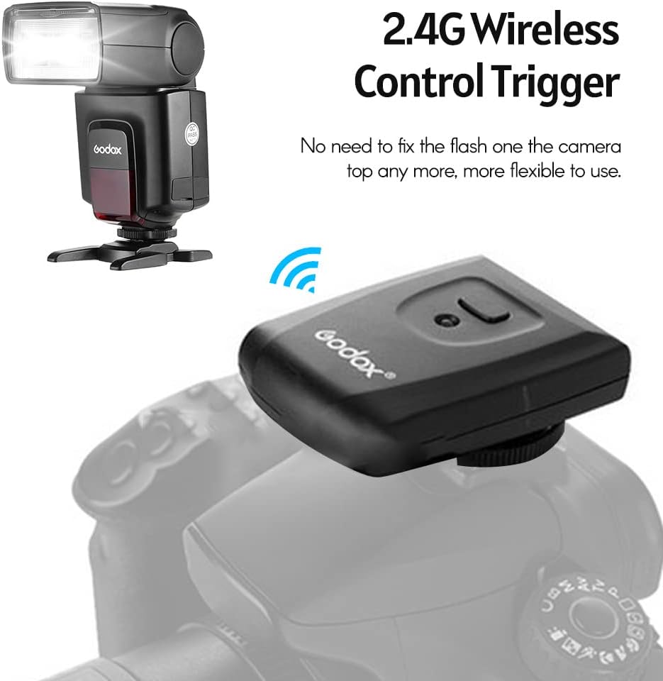
Figure 4.3: AT-16 Wireless Trigger mounted on a camera hot shoe.
This image shows the AT-16 wireless trigger placed on a camera's hot shoe, indicating its role in remotely firing the flash unit.
5. Setup
5.1. Battery Installation
- Open the battery compartment cover on the flash unit (refer to Figure 4.1).
- Insert four (4) AA batteries, ensuring correct polarity (+/-).
- Close the battery compartment cover securely.
- For the AT-16 wireless trigger, open its battery compartment and insert the required battery (typically a 23A 12V battery, though not specified in input, common for such triggers).
5.2. Mounting the Flash Unit
- Ensure the flash unit is powered off.
- Slide the flash unit's hot shoe onto your camera's hot shoe mount.
- Tighten the lock ring on the flash unit to secure it in place.
- Alternatively, use the included mini stand (Figure 5.1) to place the flash off-camera.

Figure 5.1: Front and back view of the mini stand with 1/4 inch screw.
This image shows the compact mini stand provided with the flash, featuring a 1/4 inch screw for mounting the flash unit off-camera.
6. Operating Instructions
6.1. Power On/Off
Slide the Power Switch (refer to Figure 4.1) to the "ON" position to power on the flash. Slide it to "OFF" to power off.
6.2. Mode Selection
Press the Mode Selection Button (M, S1, S2) to cycle through the available flash modes:
- M (Manual Mode): You manually set the flash power output.
- S1 (Slave Mode 1): The flash will fire in response to the first flash from a master flash. This mode is suitable for manual flash or TTL flash systems.
- S2 (Slave Mode 2): The flash will fire in response to the second flash from a master flash. This mode is designed to ignore the pre-flash of a TTL system, making it suitable for master flashes with pre-flash functions.
6.3. Power Output Control
In Manual (M) mode, use the Flash Power Level Buttons (typically '+' and '-') to adjust the power output from 1/1 (full power) down to 1/128 (lowest power) in 8 steps. The Output Level Indicator will show the current setting.

Figure 6.1: Examples of flash power output levels from 1/128 to 1/1.
This image demonstrates the effect of different flash power settings, showing how the light intensity changes from 1/128 (dimmest) to 1/1 (brightest) on a subject.
6.4. Using the Wireless Trigger (AT-16)
The AT-16 wireless trigger allows you to fire the flash unit remotely, providing greater flexibility for lighting setups.
- Mount the AT-16 transmitter onto your camera's hot shoe.
- Ensure the flash unit is powered on and set to a compatible mode (M, S1, or S2, depending on your setup).
- When you press the shutter button on your camera, the AT-16 will send a signal to the flash unit, triggering it.

Figure 6.2: Example of multiple flash units being triggered wirelessly by a camera.
This image illustrates a setup where a camera, equipped with a wireless trigger, is used to simultaneously fire multiple GODOX TT520Ⅱ flash units positioned around a subject, demonstrating off-camera lighting capabilities.
7. Maintenance
- Cleaning: Use a soft, dry cloth to clean the flash unit. For stubborn dirt, a slightly damp cloth can be used, followed by a dry one. Do not use solvents or abrasive cleaners.
- Storage: When not in use for extended periods, remove the batteries to prevent leakage. Store the flash unit in a cool, dry place, away from direct sunlight and extreme temperatures.
- Hot Shoe Contacts: Keep the hot shoe contacts clean and free of debris to ensure proper communication with the camera.
8. Troubleshooting
| Problem | Possible Cause | Solution |
|---|---|---|
| Flash does not fire. |
|
|
| Flash recycle time is slow. |
|
|
| Inconsistent flash output. |
|
|
9. Specifications
| Feature | Detail |
|---|---|
| Guide Number | GN33 (at ISO 100) |
| Flash Modes | M (Manual), S1 (Slave 1), S2 (Slave 2) |
| Power Output Control | 8 steps (1/1 to 1/128) |
| Recycle Time | Approx. 0.1-5 seconds |
| Flash Duration | 1/300s ~ 1/20000s |
| Color Temperature | 5600K ± 200K |
| Wireless Frequency | 2.4G (for AT-16 trigger) |
| Power Source | 4 x AA batteries (flash unit) |
| Product Dimensions | 2 x 7.5 x 2 inches |
| Item Weight | 15.5 ounces |
| Compatible Mountings | Canon, Nikon, Pentax, Olympus (standard hot shoe) |

Figure 9.1: GODOX TT520Ⅱ highlighting key specifications.
This image showcases the GODOX TT520Ⅱ flash unit against a city skyline, with an overlay of its main specifications: High Guide Number GN33 @ISO 100, M, S1, S2 modes, Color Temperature: 5600K+200K, and Flash Duration: 1/300s~1/20000s.
10. Warranty and Support
GODOX products are designed for reliability and performance. For warranty information and technical support, please refer to the official GODOX website or contact your local distributor.
You can also visit the official GODOX store for more information and product updates:GODOX Official Store