1. Introduction
The SoloGood Matek Systems F411-WTE F4 Flight Controller is a compact and powerful control unit designed for various RC applications, including FPV planes, airplanes, VTOL, and fixed-wing aircraft. It features a 100MHz STM32F411CEU6 microcontroller, an integrated OSD, and supports 2-6S LiPo input. This manual provides essential information for the proper setup, operation, and maintenance of your flight controller.
2. Specifications
Below are the detailed technical specifications for the F411-WTE Flight Controller:
| Feature | Detail |
|---|---|
| MCU | 100MHz STM32F411CEU6 |
| IMU | ICM42688P |
| Barometer | SPL06-001 (I2C) |
| OSD | AT7456E (SPI) |
| Blackbox | No |
| UARTs | 2x Uarts, 2x Full Softserial |
| PWM Outputs | 6 (2x Motors, 4x Servos) |
| I2C | 1x |
| ADC | 4 (VBAT, Current, RSSI, AirSpeed) |
| LEDs | 3 (FC STATUS Blue, Red; 3.3V indicator Red) |
| SBUS Input | Built-in inverter on UART2-RX |
| Camera Inputs | Switchable Dual |
| VTX/Camera Power | Vbat power ON/OFF switchable |
| PPM Receiver | Not supported |
| Power Input | 2-6S LiPo |
| Regulators | 5V 1.5A, Vx (5V/6V) 5A |
| USB Port | Vertical Type-C |
| Dimensions | 31 x 26 x 16.5 mm |
| Weight | 10g |
| INAV Target | MATEKF411TE (ICM42688P version supported by INAV 6.0 or newer) |
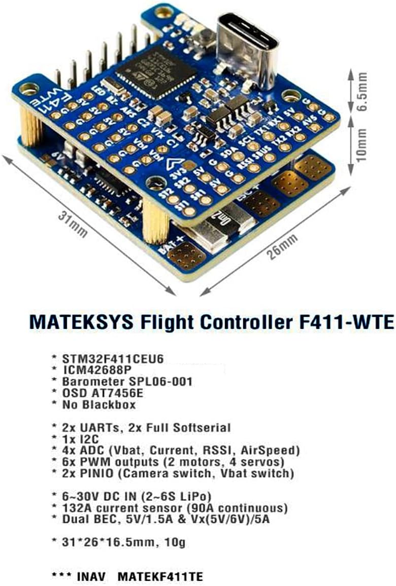
Figure 2.1: The Matek F411-WTE Flight Controller showing its compact dimensions (31mm x 26mm x 16.5mm) and key components.
3. Setup and Installation
Proper installation is crucial for the reliable operation of your flight controller. Follow these general guidelines for setup.
3.1 Physical Installation
- Mounting: Securely mount the F411-WTE Flight Controller to your aircraft frame using vibration-damping standoffs. Ensure the arrow on the board points towards the front of the aircraft.
- Power Connection: Connect the main battery (2-6S LiPo) to the designated BAT+ and BAT- pads. Observe correct polarity to prevent damage.
- ESC/Motor Connections: Connect your Electronic Speed Controllers (ESCs) to the PWM output pads (S1-S6) as per your aircraft's motor configuration (e.g., S1/S2 for motors, S3-S6 for servos in fixed-wing).
- Receiver Connection: Connect your receiver (e.g., SBUS) to the UART2-RX pad. The built-in inverter supports SBUS directly.
- Camera and VTX: Connect your FPV camera(s) to the C1/C2 inputs and your Video Transmitter (VTX) to the VTX output. Ensure Vbat power is switched ON for VTX and camera if desired.
- GPS/Other Peripherals: Connect GPS modules or other I2C/UART peripherals to their respective pads, referring to the wiring diagrams.

Figure 3.1: The Matek F411-WTE Flight Controller, showing the layout of various connection pads and the USB Type-C port.
3.2 Software Configuration
The F411-WTE Flight Controller is compatible with INAV firmware.
- Firmware Flashing: Connect the flight controller to your computer via the USB Type-C port. Use the INAV Configurator software to flash the appropriate firmware target (MATEKF411TE). Ensure you are using INAV 6.0 or newer for full ICM42688P support.
- Initial Setup: Follow the INAV Configurator's setup wizard to calibrate accelerometers, magnetometers (if external), and set up your receiver, motor/servo outputs, and flight modes.
- OSD Configuration: Configure the On-Screen Display (OSD) settings to show desired flight data, battery voltage, and other telemetry information.
- Peripheral Configuration: Enable and configure any connected peripherals such as GPS, airspeed sensors, or external compasses within the INAV Configurator.
4. Wiring Diagrams
Refer to the following diagrams for correct wiring of your flight controller with various components.

Figure 4.1: Comprehensive wiring diagram illustrating connections for ESCs, motors, battery, receiver, camera, and VTX to the F411-WTE Flight Controller. This diagram is essential for proper component integration.

Figure 4.2: Detailed layout diagram of the F411-WTE Flight Controller, indicating pin assignments, LED indicators, and component locations for reference during wiring and troubleshooting.
5. Operating Instructions
Once the flight controller is installed and configured, follow these steps for operation:
- Pre-Flight Checks: Before each flight, ensure all connections are secure, propellers are correctly installed, and the battery is fully charged. Verify control surface movements match transmitter inputs.
- Power On: Connect the main LiPo battery to the aircraft. The flight controller will power on, and LEDs will indicate its status. Wait for GPS lock if using a GPS module.
- Arming: Arm the aircraft using the configured switch on your transmitter. Ensure you are in a safe area before arming.
- Flight: Operate your aircraft according to your flight plan and local regulations. Monitor OSD data for critical information like battery voltage and altitude.
- Disarming: After landing, disarm the aircraft using your transmitter switch. Disconnect the battery immediately after flight.
6. Maintenance
Regular maintenance helps ensure the longevity and reliability of your flight controller.
- Inspection: Periodically inspect the flight controller for any physical damage, loose connections, or signs of corrosion.
- Cleaning: Keep the board clean from dust, dirt, and debris. Use a soft brush or compressed air. Avoid using liquids directly on the board.
- Firmware Updates: Check the official Matek Systems website or INAV project page for firmware updates. Updating firmware can provide new features, performance improvements, and bug fixes.
- Storage: When not in use, store the flight controller in a dry, anti-static environment, away from extreme temperatures.
7. Troubleshooting
This section addresses common issues you might encounter.
- Flight Controller Not Powering On:
- Verify battery connection and polarity.
- Check for shorts on the board or connected components.
- Ensure the USB cable is functional if powering via USB.
- No Connection to INAV Configurator:
- Install correct USB drivers (e.g., STM32 VCP drivers).
- Try a different USB cable or port.
- Ensure the flight controller is powered (either via USB or battery).
- Motors Not Spinning/Responding:
- Check ESC connections to PWM outputs.
- Calibrate ESCs.
- Verify motor direction and assignment in INAV Configurator.
- Ensure the flight controller is armed.
- OSD Not Displaying:
- Check camera and VTX connections.
- Verify OSD settings in INAV Configurator.
- Ensure video format (PAL/NTSC) matches your camera and VTX.
- Unstable Flight:
- Check for proper mounting and vibration isolation.
- Recalibrate accelerometers.
- Review PID tuning settings in INAV Configurator.
- Ensure propellers are balanced and undamaged.
- Difficulty with Soldering Small Pads:
The F411-WTE is a compact board. Use a fine-tipped soldering iron, good quality solder, and appropriate flux. Consider using magnification if needed. Ensure solder joints are clean and free of bridges, especially around sensitive areas like S1/S2 motor signal pads.
8. Warranty and Support
For warranty information, technical support, or further assistance, please refer to the official Matek Systems website or contact your retailer. Keep your proof of purchase for any warranty claims.


