1. Introduction
The WOYO CTB007 OBD2 Breakout Box is a versatile diagnostic tool designed for automotive professionals and enthusiasts. It facilitates the testing and monitoring of OBD2 (On-Board Diagnostics II) systems in 12V and 24V vehicles. This device allows for direct access to all 16 pins of the OBD2 connector, enabling detailed analysis of communication protocols, voltage levels, and circuit integrity.
Key functionalities include real-time display of communication signals, voltage measurement for each pin, and the ability to connect external diagnostic equipment like multimeters, oscilloscopes, or diagnostic scanners. The integrated 27-inch extension cable provides flexibility during use.
2. What's in the Box
Upon unboxing your WOYO CTB007, please ensure all components are present:
- 1 x WOYO CTB007 OBD2 Breakout Box
- 10 x Banana Pins (2mm)
- 1 x User Manual
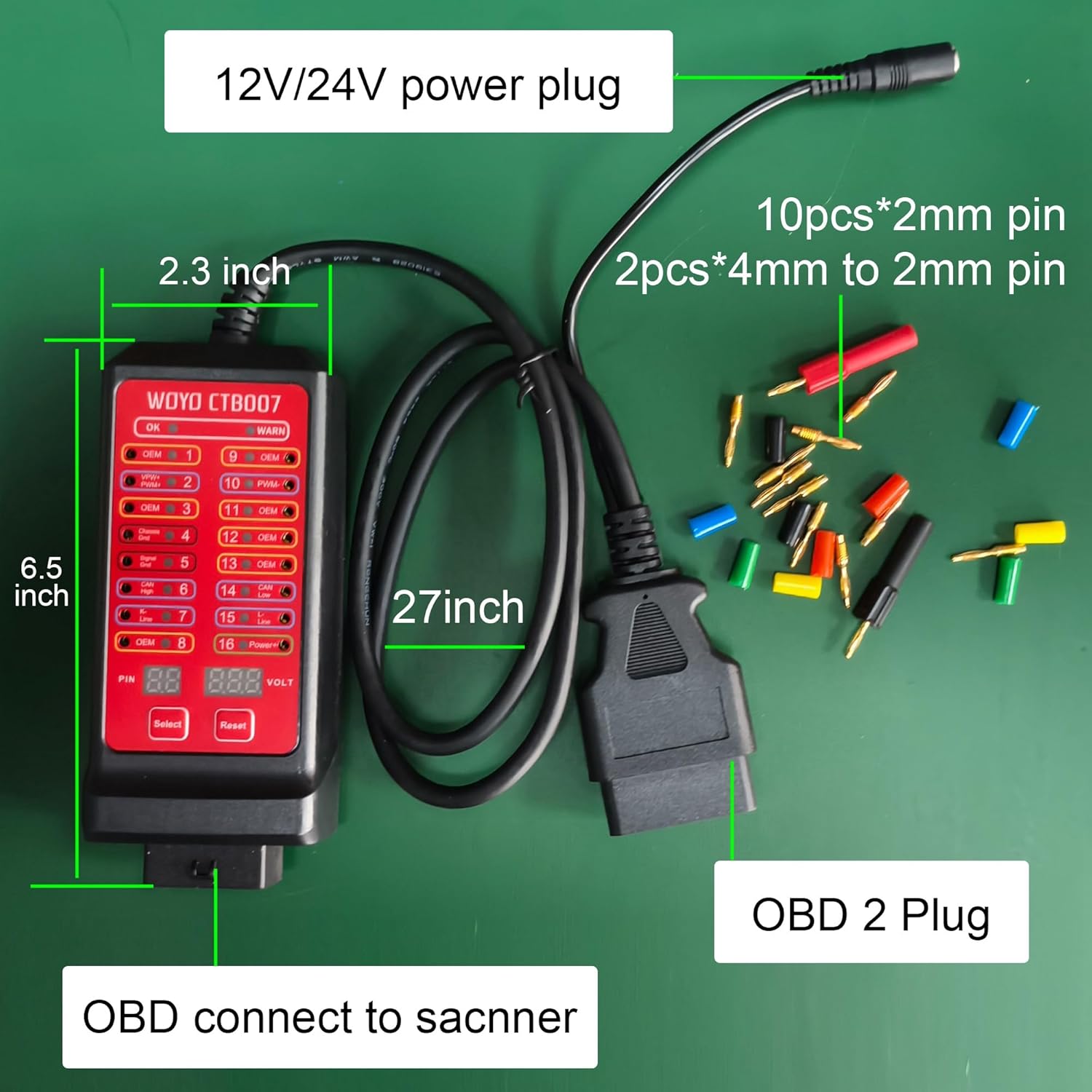
Figure 2.1: WOYO CTB007 components including the main unit, 27-inch cable, and 10 banana pins. The device dimensions are approximately 6.5 inches in length and 2.3 inches in width.
3. Setup
To begin using your WOYO CTB007, follow these steps:
- Locate the OBD2 Port: The OBD2 diagnostic port is typically located under the dashboard on the driver's side of the vehicle.
- Connect the Breakout Box: Plug the OBD2 connector of the WOYO CTB007 into your vehicle's OBD2 port. Ensure a secure connection.
- Power On (if necessary): The device usually draws power directly from the vehicle's OBD2 port. If the device does not power on, ensure the vehicle's ignition is in the 'ON' position (engine off). For off-vehicle testing or if the vehicle battery is dead, an external 8V-30V power supply can be connected via the DC power input jack.

Figure 3.1: The WOYO CTB007 connected to a vehicle's OBD2 port, demonstrating its use with a multimeter for pin voltage measurement. The 27-inch cable provides extended reach.
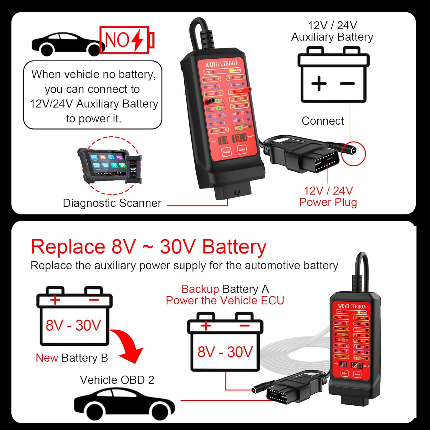
Figure 3.2: Illustration of power supply options for the CTB007. It can be powered by the vehicle's OBD2 port or an external 12V/24V auxiliary battery. It also supports maintaining ECU power during battery replacement using an external 8V-30V backup battery.
4. Operating Instructions
4.1. Pin Voltage Testing
The CTB007 features a digital voltage display and individual LED indicators for each of the 16 pins. This allows for real-time monitoring of voltage and communication signals.
- Digital Voltage Display: The device displays the voltage of the selected pin. Use the "Select" button to cycle through the pins (1-16) and the "Reset" button to reset the selection (defaults to pin 16).
- LED Indicators: Each pin has an associated LED. A lit LED indicates activity or voltage on that pin. Green LEDs typically indicate power or ground, while other colors may indicate communication signals.
- High/Low Voltage Alarm: The device includes an alarm function for detecting abnormally high or low voltage on pin 16 (battery positive), alerting the user to potential issues.
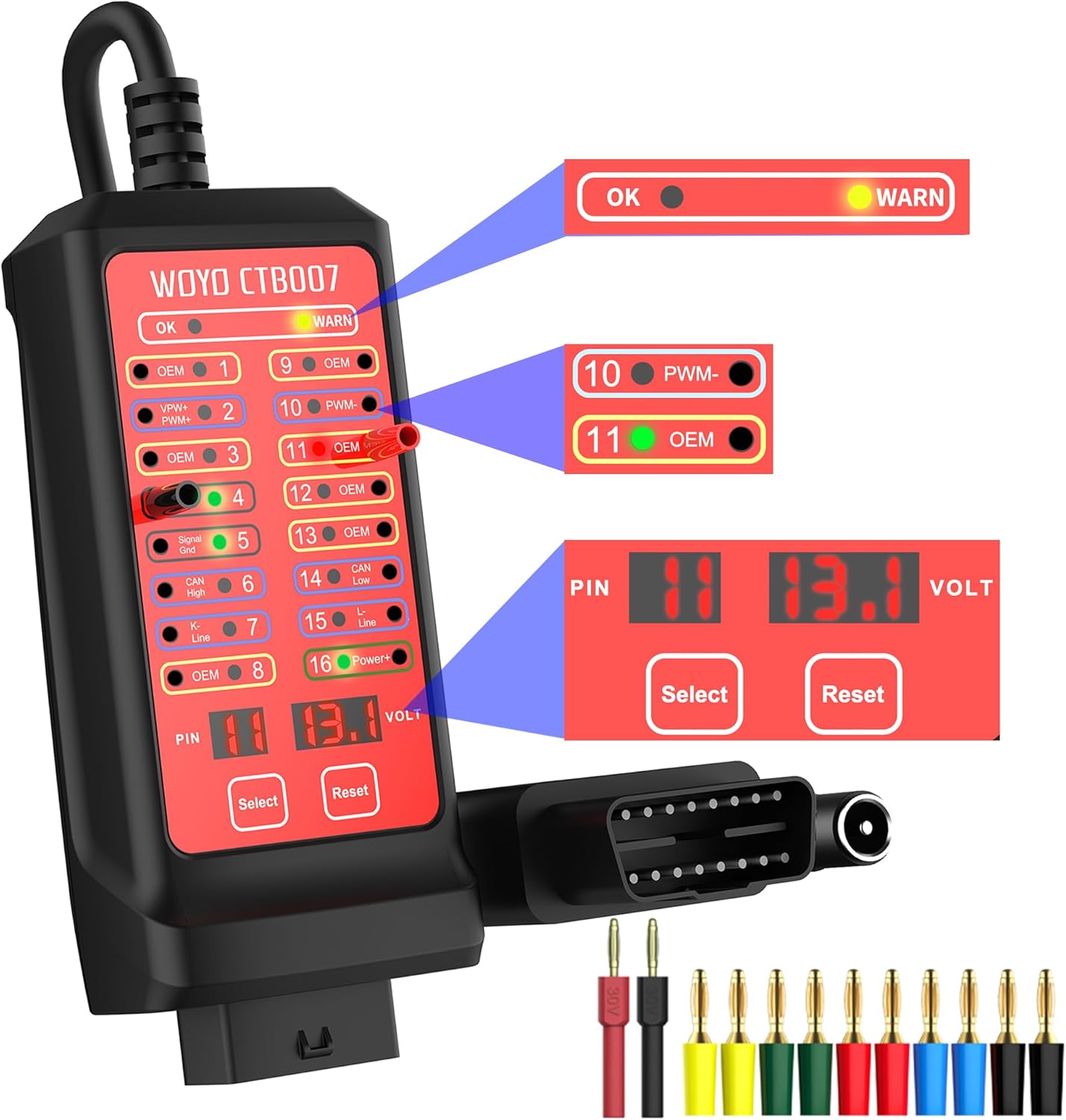
Figure 4.1: Close-up of the WOYO CTB007 interface, highlighting the digital voltage display, "Select" and "Reset" buttons, and individual LED indicators for each of the 16 OBD2 pins.

Figure 4.2: Detailed view of the voltage display area on the CTB007, showing the PIN number and corresponding voltage. The "Select" button changes the PIN number, and "Reset" defaults to PIN 16 (Power+).
4.2. Connecting External Diagnostic Tools
The CTB007 provides access points for connecting various diagnostic instruments:
- Multimeter/Oscilloscope: Use the provided banana pins (2mm) to connect a multimeter or oscilloscope to any of the 16 pins for detailed signal analysis. This is useful for verifying communication protocols and signal integrity.
- Diagnostic Scanner/PC Software: The breakout box acts as an extension, allowing you to connect your diagnostic scanner or PC-based diagnostic software (e.g., VCDS, Delphi) to the vehicle's OBD2 system while simultaneously monitoring pin activity.

Figure 4.3: Connectivity diagram illustrating how the CTB007 integrates with multimeters, oscilloscopes, diagnostic scanners, and PC software for comprehensive vehicle diagnostics.

Figure 4.4: Demonstrates the flexibility of the CTB007 for both on-vehicle testing (cars, trucks, motorcycles) and off-vehicle bench testing of CAN BUS modules (ECU/TCU/PEPS/IP/HMI).
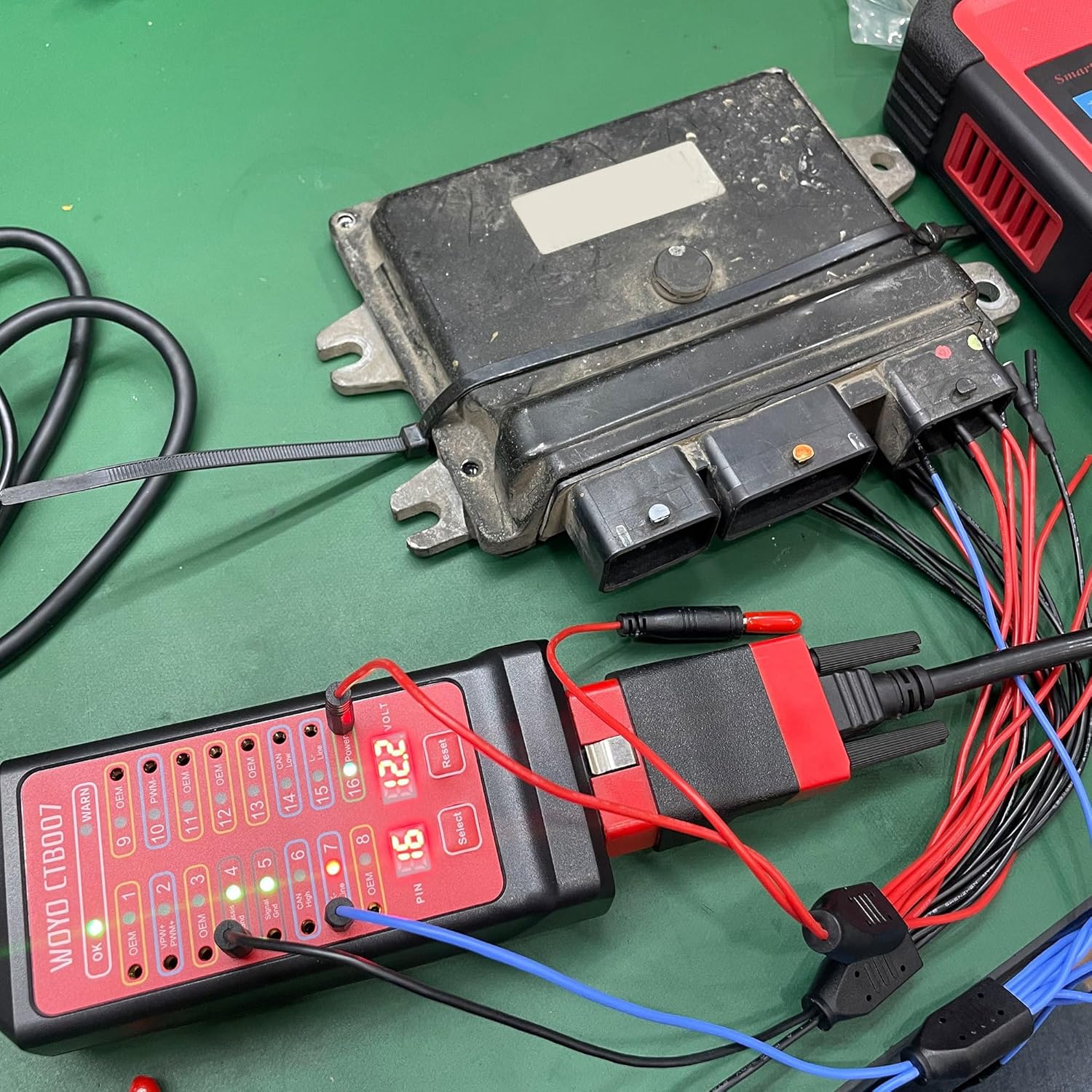
Figure 4.5: The CTB007 connected to an Electronic Control Unit (ECU) on a workbench, allowing for direct testing of CAN BUS modules.
4.3. Pin Definitions
Understanding the function of each pin on the OBD2 connector is crucial for effective diagnostics. The CTB007 provides a visual representation and access to these pins.

Figure 4.6: Standard OBD2 16-pin definitions, indicating common assignments such as CAN High, CAN Low, K-Line, L-Line, Chassis Ground, Signal Ground, and Battery Positive. Pins marked "Self-Define by car manufacturers" may vary in function depending on the vehicle.
5. Troubleshooting
The WOYO CTB007 is designed to assist in diagnosing common OBD2 communication and power issues:
- No Power to CTB007:
- Ensure the vehicle's ignition is 'ON'.
- Check pin 16 (Battery Positive) for 12V/24V using the CTB007's voltage display or an external multimeter.
- Verify pin 4 (Chassis Ground) and pin 5 (Signal Ground) for proper grounding.
- If no power is detected, inspect the vehicle's OBD2 port wiring or fuses.
- Diagnostic Scanner Cannot Communicate:
- Use the CTB007 to check for communication signals (e.g., CAN High, CAN Low, K-Line, L-Line) on the relevant pins. Flashing LEDs indicate active communication.
- Test for short circuits or reverse polarity on the OBD2 pins using the CTB007 before connecting the scanner.
- Ensure the diagnostic scanner itself is functioning correctly by testing it on a known good vehicle.
- Intermittent Communication:
- Monitor the LED indicators for communication pins for any flickering or inconsistent activity, which may suggest loose connections or wiring issues.
- Check for stable voltage on pin 16 and stable grounds on pins 4 and 5.
6. Specifications
| Feature | Detail |
|---|---|
| Model | CTB007 |
| Brand | WOYO |
| Compatibility | 12V/24V OBD2 Systems (Car, Truck, Motorcycle with adapter) |
| Cable Length | 27 inches (approx. 70 cm) |
| Input Voltage Range | 8V-30V (for external power supply) |
| Dimensions | 5.17 x 2.5 x 1.25 inches |
| Weight | 10.6 ounces |
| Features | Digital Voltage Display, LED Pin Indicators, High/Low Voltage Alarm, Short Circuit Protection |
7. Official Product Videos
Watch these official videos from WOYO SMART for visual guidance on using your CTB007 OBD2 Breakout Box.
How to use CTB007 CAN Tester Box/OBD2 Breakout box?
Video 7.1: This video provides a step-by-step guide on the basic operation and functionality of the WOYO CTB007 CAN Tester Box, also known as the OBD2 Breakout Box.
WOYO Diagnostic Tool OBD2 16 Pin Break Out Box CAN Tester
Video 7.2: An overview of the WOYO Diagnostic Tool, highlighting its features as an OBD2 16-pin breakout box and CAN tester for various diagnostic scenarios.
CTB007 use on Car or Motorcycle.
Video 7.3: This video demonstrates the practical application of the CTB007 on both cars and motorcycles, showcasing its versatility across different vehicle types.
8. Maintenance
To ensure the longevity and optimal performance of your WOYO CTB007, follow these maintenance guidelines:
- Cleaning: Wipe the device with a soft, dry cloth. Avoid using abrasive cleaners or solvents that could damage the casing or screen.
- Storage: Store the breakout box in a cool, dry place away from direct sunlight and extreme temperatures. Keep it in its original packaging or a protective case when not in use.
- Cable Care: Avoid sharp bends or kinks in the extension cable. Do not pull the cable to disconnect the device; always grasp the connector.
9. Warranty and Support
For warranty information, technical support, or service inquiries regarding your WOYO CTB007, please refer to the contact details provided in the product packaging or visit the official WOYO website. Keep your purchase receipt as proof of purchase for warranty claims.
You can also visit the WOYO Store on Amazon for additional product information and support resources.


