Introduction
The FrSky TD R18 is a Tandem dual-band receiver designed for remote control applications, offering simultaneous 2.4GHz and 900MHz operation. It features 18 configurable channel ports and advanced functionalities like Black Box and 4ms Race Mode with Telemetry. This manual provides essential information for the proper setup, operation, and maintenance of your TD R18 receiver.

Image: The FrSky TD R18 Tandem Dual-Band Receiver, showcasing its compact design and multiple ports.
Features
- Simultaneous working dual-band TD mode
- Triple antenna design for multi-directional coverage
- Black Box function for flight data recording
- Built-in Power Switch
- Built-in current and voltage sensors
- 4ms Race Mode with Telemetry
- Long control range (up to 50KM – 100KM)
- Over-The-Air (OTA) FW update capability
- 18 Configurable Channel Ports:
- CP1: PWM / SBUS Out / FBUS / S.Port / SBUS In (Redundancy Function)
- CP2-18: PWM / SBUS Out / FBUS / S.Port
- Dual XT30 Power Input Connector
- Triple 2.4G/900M Antenna System: 1* Interior 2.4G chip antenna, 1* External 2.4G antenna (IPEX1), 1* Newly designed 900M antenna
Specifications
| Parameter | Value |
|---|---|
| Frequency | 2.4GHz & 900MHz |
| Dimensions (L*W*H) | 53*40*16mm (2.09 x 1.57 x 0.63 inches) |
| Weight | 28.9g (1.02 ounces) |
| Operating Voltage | 4-10V (Recommended 2S Li batteries) |
| Operating Current | ≤185mA@5V |
| Continuous Current | ≤30A (power the device) |
| Instantaneous Current | ≤60A (power the device) |
| Compatibility | Tandem series radio & TD protocol capable RF module |
Package Contents
Upon opening the package, you should find the following items:
- FrSky TD R18 Receiver
- 2.4GHz Antennas (external)
- 900MHz Antenna
- Wiring Harness (servo cables)
- Optional: External Switch Module (may be included depending on package variant)
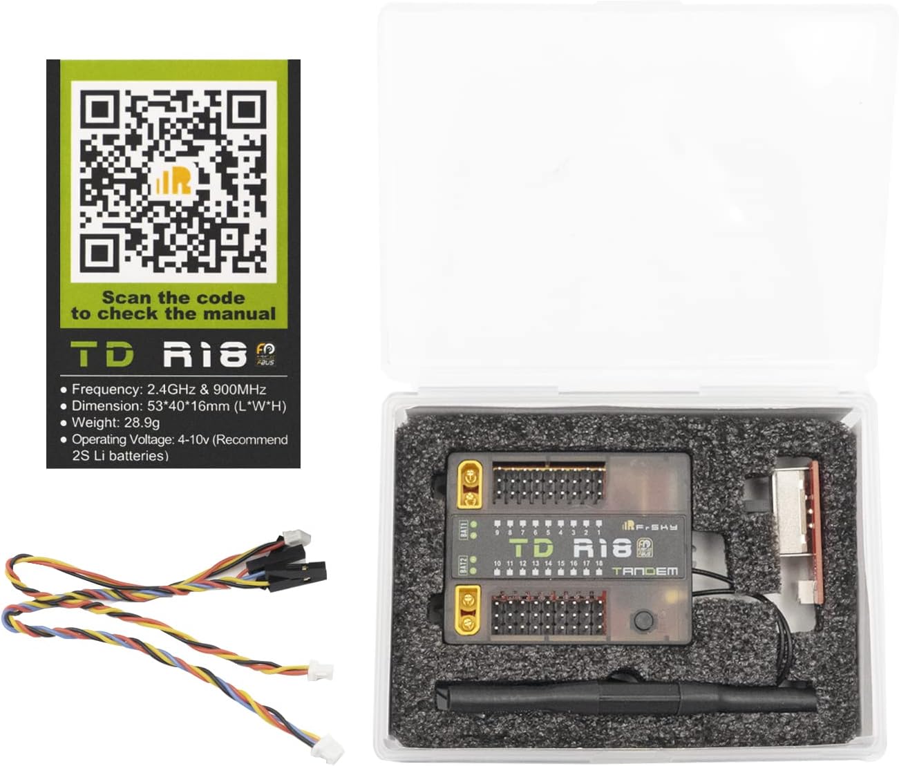
Image: Contents of the FrSky TD R18 package, including the receiver, antennas, and wiring.
Setup
Antenna Installation
The TD R18 receiver features a triple antenna design for optimal signal reception. Ensure all antennas are securely connected and positioned for multi-directional coverage. One interior 2.4G chip antenna, one external 2.4G antenna (IPEX1), and one newly designed 900M antenna are included. Refer to the diagram below for proper antenna connection points and orientation.

Image: Diagram illustrating the antenna connection points on the FrSky TD R18 receiver, showing 2.4G and 900M antenna ports.

Image: Diagram showing the radiation pattern for the 900MHz receiver antenna, indicating optimal orientation for signal reception.
Wiring
The TD R18 has 18 configurable channel ports (CP1-CP18) and dual XT30 power input connectors. Connect your servos and other peripherals to the appropriate channel ports. CP1 supports PWM, SBUS Out, FBUS, S.Port, and SBUS In for redundancy. CP2-18 support PWM, SBUS Out, FBUS, and S.Port. For power, use the dual XT30 connectors, ensuring proper polarity. The receiver operates between 4-10V.

Image: Wiring diagram for the FrSky TD R18 receiver, detailing connections for channels, power, and other ports.

Image: Close-up of the FrSky TD R18 receiver highlighting the dual XT30 power input connectors.
Binding Procedure
To bind the TD R18 receiver to your FrSky Tandem series radio or TD protocol capable RF module, follow these steps:
- Put your transmitter into bind mode.
- Power on the receiver while holding the F/S button. Release the button when the Green LED and Red LED are flashing simultaneously.
- Select [BIND] on your transmitter. The Green LED on the receiver will flash, and the Red LED will be off, indicating successful binding.
- Power cycle the receiver. The Green LED will be on, and the Blue LED will flash, indicating successful binding and normal operation.
- If binding fails, repeat the process.
Operation
LED Status Indicators
The receiver uses Green, Blue, and Red LEDs to indicate its status. Refer to the table below for interpretations:
| Green LED | Blue LED | Red LED | Status |
|---|---|---|---|
| On | Off | On | Register |
| Flash | Off | Flash | Register successfully |
| On | Off | Off | Bind |
| On | Flash | Off | Bind successfully |
| On | Flash | Off | Working normally |
| Off | Off | On | Failsafe |

Image: Table detailing the meaning of different LED light combinations on the FrSky TD R18 receiver.
Flight Data Record (Black Box)
The Black Box function records flight data. Access this feature through your compatible FrSky transmitter's RF System menu under 'Flight Data Record' to review various reset cases and operational parameters. This can be useful for diagnostics and performance analysis.

Image: Screenshot of a FrSky transmitter interface showing the 'Flight Data Record' menu option.
Range Check
Perform a range check before each flight. In your transmitter's RF System menu, select 'Range Check'. This will display the 2.4G and 900M signal strength (VFR and RSSI) to ensure adequate control range. Always conduct a range check in a safe, open area.

Image: Screenshot of a FrSky transmitter interface displaying the 'Range Check' results, showing 2.4G and 900M signal values.
Maintenance
To ensure the longevity and reliable performance of your FrSky TD R18 receiver, follow these maintenance guidelines:
- Keep the receiver clean and free from dust, dirt, and moisture. Use a soft, dry cloth for cleaning.
- Regularly inspect antenna connections and wiring for any signs of wear, fraying, or damage. Replace damaged components immediately.
- Ensure proper ventilation around the receiver to prevent overheating, especially during extended operation.
- Avoid exposing the receiver to extreme temperatures or direct sunlight for prolonged periods.
Troubleshooting
If you encounter issues with your TD R18 receiver, consider the following:
- Receiver Not Binding: Ensure your transmitter is in bind mode. Verify that the F/S button on the receiver is pressed correctly during power-up. Check the LED status indicators for specific binding feedback.
- Signal Loss: Confirm that all antennas are securely connected and properly positioned for optimal reception. Check for any obstructions or sources of interference in your operating environment.
- No Power: Verify that the power supply voltage is within the specified 4-10V range and that the XT30 connectors are properly seated with correct polarity. Inspect power cables for damage.
- Intermittent Operation: Check all wiring connections for looseness or damage. Ensure the receiver is not experiencing excessive vibration or physical stress.
Warranty and Support
For detailed warranty information, technical support, and firmware updates, please visit the official FrSky website or contact your local authorized FrSky dealer. A digital version of this manual and additional resources can be found on the product page:


