1. Introduction
This instruction manual provides essential information for the safe and efficient installation, operation, and maintenance of your Hormann RotaMatic P 2-1 single-leaf swing gate operator. Please read this manual thoroughly before beginning any installation or operation procedures. Keep this manual in a safe place for future reference.
2. Safety Instructions
Important: Failure to follow these safety instructions may result in serious injury or property damage.
- Installation must be performed by qualified personnel in accordance with local electrical and building codes.
- Do not allow children to play with or operate the gate controls.
- Keep hands, feet, and clothing clear of the gate and operator while the gate is in motion.
- Ensure all safety devices (e.g., photocells, safety edges) are correctly installed and functioning before operating the gate.
- Disconnect power to the operator before performing any maintenance or repairs.
- Never attempt to repair the operator yourself. Contact qualified service personnel.
- The gate operator is designed for single-leaf swing gates only. Do not use for other applications.
- Regularly inspect the gate and operator for signs of wear, damage, or misalignment.
3. Package Contents
Verify that all components are present and undamaged before proceeding with installation.
- 1x Hormann RotaMatic P 2-1 Gate Operator
- 1x Manual Transmitter (remote control)
- 1x Receiver unit
- 1x Bulb (if applicable, without heating)
- Mounting hardware (screws, brackets, etc.)
- Instruction Manual (this document)
4. Setup and Installation
The installation of the RotaMatic P 2-1 gate operator requires technical knowledge and adherence to safety standards. It is highly recommended that installation be carried out by a certified professional.
4.1 Pre-Installation Checks
- Ensure the gate operates smoothly manually and is properly balanced.
- Verify the gate dimensions and weight are within the operator's specifications (max. height 2000 mm, width 1000-2500 mm, weight up to 400 kg).
- Confirm availability of a 230-240 V AC power supply near the installation point.
4.2 Mounting the Operator
Mount the operator arm to the gate post and gate leaf using the provided brackets and hardware. Ensure correct alignment and secure fastening to allow for smooth gate movement without obstruction. Refer to the detailed diagrams in the separate installation guide for precise measurements and mounting positions.
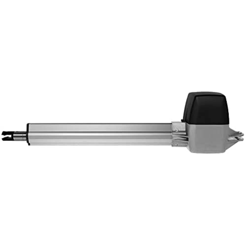
Figure 1: Hormann RotaMatic P 2-1 Gate Operator. This image shows the compact design of the gate operator unit, typically mounted on a gate post.
4.3 Electrical Connection
Connect the operator to the main power supply (230-240 V AC) and the control unit. Ensure all wiring is done according to the electrical diagram provided in the installation guide and complies with local regulations. Install all necessary safety devices, such as photocells, before initial power-up.
5. Operating Instructions
5.1 Initial Setup and Programming
After installation and electrical connection, the operator requires initial programming to learn the gate's travel limits and force settings. Refer to the control unit's specific programming instructions for detailed steps. This typically involves a learning cycle where the gate opens and closes fully.
5.2 Basic Operation
- Opening the Gate: Press the designated button on your manual transmitter (remote control). The gate will begin to open.
- Closing the Gate: Press the designated button on your manual transmitter. The gate will begin to close.
- Stopping the Gate: Press the button again while the gate is in motion to stop it.
- Automatic Closing: If enabled, the gate will automatically close after a set period once fully opened. This delay can be adjusted in the control unit settings.
5.3 Special Features
- Adjustable Speed: The RotaMatic P 2-1 allows for individual adjustment of the gate speed, ensuring smooth operation for various gate sizes.
- Soft Start and Soft Stop: This feature ensures gentle acceleration and deceleration of the gate, reducing wear and tear and providing quieter operation.
- Force Limitation: The operator is equipped with force limitation, which detects obstacles and reverses the gate's direction to prevent injury or damage.
- Emergency Release: In case of power failure, locate and operate the emergency release mechanism to manually open or close the gate. Refer to the control unit manual for its exact location and procedure.
6. Maintenance
Regular maintenance ensures the longevity and safe operation of your gate operator.
- Monthly:
- Check the gate's manual operation for smooth movement and proper balance.
- Inspect all mounting hardware for tightness.
- Clean photocells and other safety sensors to ensure they are free from dirt or obstructions.
- Quarterly:
- Test the force limitation feature by placing a soft, non-damaging object in the gate's path during closing. The gate should reverse.
- Inspect all cables and wiring for signs of wear or damage.
- Annually:
- Have the system inspected by a qualified technician.
- Lubricate moving parts of the gate (hinges, rollers) as recommended by the gate manufacturer.
Do not use harsh chemicals or abrasive materials for cleaning.
7. Troubleshooting
Before contacting customer support, review the following common issues and their solutions.
| Problem | Possible Cause | Solution |
|---|---|---|
| Gate does not respond to remote control. |
|
|
| Gate opens but does not close. |
|
|
| Gate operates slowly or erratically. |
|
|
If the problem persists after attempting these solutions, please contact Hormann customer support or a qualified technician.
8. Technical Specifications
| Feature | Detail |
|---|---|
| Model Number | 4510968 |
| Suitable for | Single-leaf swing gates |
| Max. Gate Height | 2000 mm |
| Min.-Max. Gate Width | 1000-2500 mm |
| Max. Gate Leaf Weight | 400 kg |
| Motor Type | 24 V DC |
| Mains Connection | 230-240 V AC |
| Nominal Force | 540 N |
| Max. Push/Pull Force | 2700 N |
| Spindle Speed | Approx. 25 mm/s |
| Housing Material | Aluminium / Die-cast zinc / Glass fibre reinforced plastic |
| Temperature Range | -20 °C to +60 °C |
| Protection Class (Operator) | IP 44 |
| Protection Class (Control Box) | IP 65 |
| Control Type | Pulse control with force limitation, soft start/stop |
| Display | Dual 7-segment display |
| Automatic Feed Adjustable | Yes |
| Connectable Safety Devices | 2 |
| Product Dimensions (L x W x H) | 80 x 24.5 x 23 cm |
| Product Weight | 11 kg |
| Country of Origin | Germany |
9. Warranty and Support
For warranty information, please refer to the documentation provided with your purchase or contact your authorized Hormann dealer. Hormann products are manufactured to high-quality standards. In the unlikely event of a defect, please contact your supplier or Hormann customer service for assistance.
For technical support, spare parts, or service inquiries, please visit the official Hormann website or contact their authorized service partners.


