1. Introduction
This manual provides essential information for the safe and effective operation of your Neoteck Digital Dial Gauge, Model NTK021. This precision instrument is designed for accurate measurement of small linear distances in mechanical and industrial processes, as well as laboratory settings. It is ideal for checking tolerance levels during the inspection of mechanical parts.
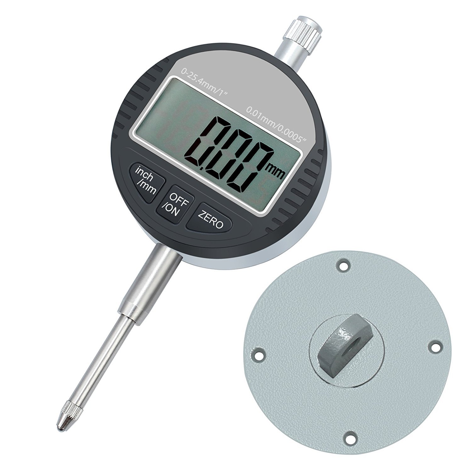
Figure 1: Neoteck Digital Dial Gauge and included back cover.
2. Safety Information
Please read and understand all safety instructions before using the device. Failure to follow these instructions may result in injury or damage to the instrument.
- Avoid dropping or impacting the gauge, as this can damage the precision components.
- Keep the indicator face clean and prevent liquids from entering the internal mechanism.
- Do not remove or modify any part of the indicator unless specified in this manual.
- Ensure the gauge is securely mounted when in use to prevent accidental movement.
- Do not use the gauge in environments with excessive dust, humidity, or extreme temperatures.
3. Product Overview
The Neoteck Digital Dial Gauge features a clear LCD display and robust construction for reliable measurements. Key components and features are outlined below.
3.1 Components
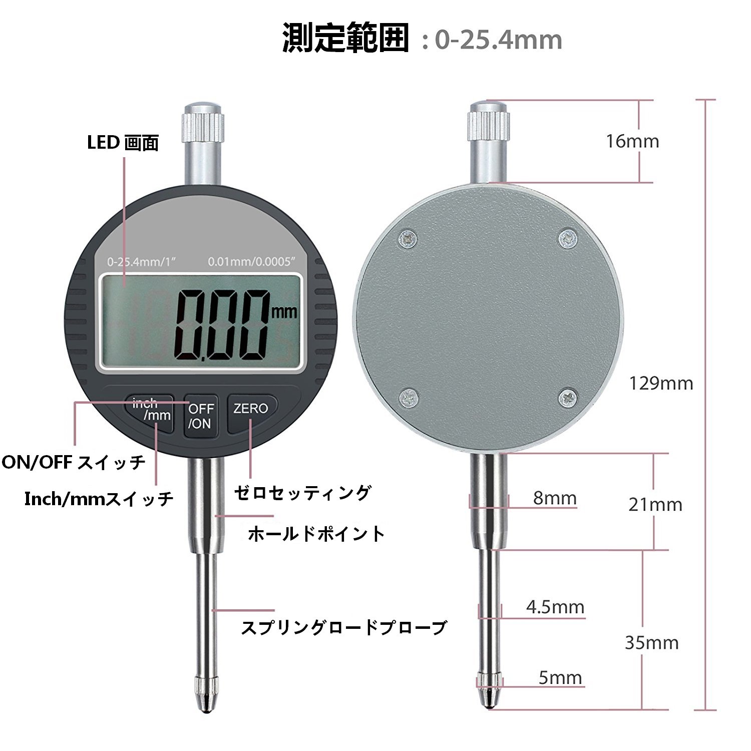
Figure 2: Digital Dial Gauge components and dimensions.
- LCD Screen: Displays measurement readings.
- ON/OFF Switch: Powers the device on or off.
- Inch/mm Switch: Toggles between imperial (inches) and metric (millimeters) units.
- ZERO Button: Sets the current position as the zero reference point.
- Lifting Cap: Used to raise the plunger easily.
- Spindle (Plunger): The movable rod that contacts the surface being measured.
- Contact Probe: The tip of the plunger that makes contact. Version M2.5, interchangeable.
- Back Cover: Allows for mounting the gauge to various fixtures, such as a magnetic base.
3.2 Data Output and Battery Access

Figure 3: Data output and battery access points.
- Socket A (Data Output Interface): Enables data transfer to a computer.
- Socket B (Battery Capsule): Facilitates easy battery replacement.
4. Setup
Before taking measurements, the digital dial gauge needs to be properly set up, often with a magnetic base for stability.
4.1 Attaching the Back Cover
The included back cover allows for versatile mounting options. It can be attached to the rear of the dial gauge and then secured to a magnetic base or other fixture.

Figure 4: Digital Dial Gauge with back cover for mounting.
4.2 Using a Magnetic Base (Optional)
For stable and precise measurements, it is recommended to use the dial gauge with a magnetic base. The magnetic base allows for flexible positioning and secure attachment to ferrous surfaces.
Video 1: Demonstration of a magnetic base being activated and deactivated. This shows how the base securely attaches to a metal surface and can be easily released.
To attach the dial gauge to a magnetic base:
- Ensure the magnetic base is clean and free of debris.
- Attach the dial gauge to the magnetic base's arm using the appropriate clamp.
- Position the magnetic base on a stable ferrous surface.
- Turn the knob on the magnetic base to the "ON" position to activate the magnet, securing the base in place.
- Adjust the arm of the magnetic base to position the dial gauge's probe over the measurement point. Tighten all adjustment knobs to secure the gauge's position.
5. Operating Instructions
Follow these steps to take accurate measurements with your digital dial gauge.
5.1 Basic Measurement
- Power On: Press the ON/OFF button to turn on the gauge.
- Select Units: Press the inch/mm button to switch between millimeters (mm) and inches (in) as needed.
- Zeroing:
- Position the contact probe against the reference surface or the lowest point of the object to be measured.
- Press the ZERO button. The display will show "0.00" (or "0.000" in inches), establishing this point as your zero reference.
- Take Measurement: Move the probe to the point you wish to measure. The display will show the deviation from your zero reference.
- Power Off: Press the ON/OFF button again to turn off the gauge when not in use.

Figure 5: Digital Dial Gauge measuring a component.
5.2 Application Examples
The digital dial gauge can be used for various precision measurement tasks, such as checking runout, flatness, and parallelism.
Video 2: Demonstration of a digital dial indicator in various measurement applications, including checking runout on a rotating shaft and measuring surface variations.
6. Maintenance
Proper maintenance ensures the longevity and accuracy of your digital dial gauge.
- Cleaning: Wipe the gauge with a soft, dry cloth after each use. Do not use solvents or abrasive cleaners.
- Storage: Store the gauge in its protective case in a dry, clean environment away from direct sunlight and extreme temperatures.
- Battery Replacement: The gauge uses an LR44 battery. If the display becomes dim or erratic, replace the battery by opening Socket B (Battery Capsule) as shown in Figure 3. Ensure correct polarity.
- Probe Replacement: The M2.5 contact probe is interchangeable. If the probe becomes worn or damaged, it can be unscrewed and replaced with a new one.
7. Troubleshooting
| Problem | Possible Cause | Solution |
|---|---|---|
| Display is blank or dim. | Low or dead battery. | Replace the LR44 battery. |
| Erratic or incorrect readings. |
|
|
| Gauge does not turn on. | Battery incorrectly installed or completely dead. | Check battery installation and replace if necessary. |
8. Specifications
| Feature | Specification |
|---|---|
| Brand | Neoteck |
| Model Number | NTK021 |
| Measurement Accuracy | 0.01 mm |
| Measurement Range | 0-25.4 mm |
| Product Weight | 300 g |
| Package Dimensions | 17.5 x 8.4 x 6.2 cm |
| Included Accessories | Digital Indicator, Back Cover |
| Battery Type | LR44 (not included) |
9. Warranty and Support
The Neoteck Digital Dial Gauge comes with an 18-month warranty period from the date of purchase. For warranty claims, technical support, or any inquiries regarding the product, please contact Neoteck customer service through your retailer or the official Neoteck website.
For more information about Neoteck products, visit the official store: Neoteck Store


