
PowMr MPPT 60A/12V 24V 36V 48V
Contents
PowMr 60A MPPT Solar Charge Controller User Manual
Model: MPPT 60A/12V 24V 36V 48V | Brand: PowMr
1. Overview
The PowMr 60A MPPT Solar Charge Controller is an advanced maximum power point tracking (MPPT) device designed to optimize the power output from your solar panels to efficiently charge your battery bank. It supports 12V, 24V, 36V, and 48V battery systems and is compatible with various battery types including lead-acid (AGM, Gel, Flooded) and Lithium batteries. This controller features a detailed LCD display for easy monitoring and multiple protection functions to ensure safe and reliable operation of your solar power system.

Figure 1: Front view of the PowMr 60A MPPT Solar Charge Controller.
2. Key Features
- Advanced MPPT Technology: Achieves up to 98% tracking efficiency and 99% conversion efficiency for optimal power harvesting from solar panels.
- Wide Voltage and Power Support: Supports PV input voltage up to 190V and solar power up to 2800W (for 48V systems).
- Multi-Voltage Battery Compatibility: Automatically detects and works with 12V, 24V, 36V, and 48V battery systems.
- Versatile Battery Type Support: Compatible with Sealed, Gel, Flooded, and Lithium (LFP) batteries, with pre-set and user-defined charging parameters.
- 4-Stage Intelligent Charging: Features Bulk Charge, Boost Charge, Float Charge, and Equalization stages for rapid, efficient, and safe battery charging, prolonging battery lifespan.
- Comprehensive Protections: Includes short circuit, overcurrent, reverse polarity, over-temperature, overload, and PV array short circuit protections.
- User-Friendly LCD Display: Provides detailed real-time working status and parameters on a single screen, with easy navigation via four buttons.

Figure 2: Comparison highlighting the advanced features of the PowMr MPPT controller.

Figure 3: Illustration of the high tracking and conversion efficiency of the MPPT technology.
3. Setup and Installation
3.1 Safety Precautions
- Ensure all connections are secure and correct polarity is observed.
- Install appropriate circuit breakers for both battery and solar panel connections.
- Mount the controller in a well-ventilated area, away from direct sunlight and moisture.
- Always disconnect the solar panels first, then the battery, when performing maintenance or disconnection.
3.2 Installation Steps
- Mount the Controller: Securely mount the controller to a flat surface using four screws.
- Remove Terminal Cover: Carefully remove the orange terminal screw cover from the bottom of the controller.
- Loosen Terminal Screws: Loosen all terminal screws to prepare for wiring.
- Install Battery Circuit Breaker: Install a suitable battery circuit breaker between the controller and the battery.
- Connect the Battery: Connect the battery cables to the controller's battery terminals (positive to positive, negative to negative). Ensure the battery breaker is open during connection.
- Connect Photovoltaic Input: Connect the solar panel cables to the controller's PV terminals (positive to positive, negative to negative).
- Connect DC Load (Optional): If using a DC load directly from the controller, connect its cables to the load terminals.
- Confirm Connections: Double-check all cable connections for security and correct polarity.
- Close Terminal Cover: Replace the orange terminal screw cover.
- Start the Controller: Close the battery circuit breaker first, then the solar panel circuit breaker. The controller will power on.

Figure 4: Securing the controller to the mounting surface.

Figure 5: Removing the terminal cover to access wiring ports.
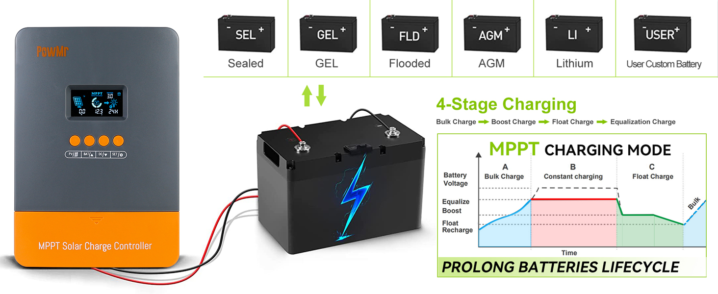
Figure 6: Loosening the terminal screws before inserting wires.

Figure 7: Installing the battery circuit breaker for safety.

Figure 8: Connecting the battery to the charge controller terminals.

Figure 9: Connecting the solar panel input to the charge controller.

Figure 10: Comprehensive wiring diagram for the solar charge controller.
Video 1: Quick Installation Wiring Guide for PowMr 60A MPPT Controller. This video demonstrates the step-by-step process of wiring the solar charge controller, including connecting the battery and solar panels.
4. Operating Instructions
4.1 LCD Display Overview
The controller features a '0 Layer Display' which means all essential working information (PV, Battery, Load) is displayed on a single screen for easy monitoring.

Figure 11: Detailed LCD display showing real-time system parameters.
4.2 Button Functions and Settings
The controller has four buttons for navigation and setting adjustments:
- PV Button: Press to browse specific parameters of PV (voltage, current, power). This button is for viewing only; no setting function.
- BAT/Up Button: Press to view battery information (voltage, current). Long press to modify battery type or charging parameters (e.g., C13.6V). Use Up/Down buttons to adjust value, then SET to confirm.
- DC/Down Button: Used for load mode setting. Long press to make 'load value' flash, then use Up/Down buttons to modify.
- SET Button: Used to save/reset parameters after modification.
Video 2: Instruction of PowMr M60's setting and work mode. This video provides a detailed guide on how to navigate the controller's menu and adjust various settings using the physical buttons.
4.3 Charging Modes
The controller utilizes a 4-stage charging algorithm to ensure optimal battery health and longevity:
- Bulk Charge: Initial stage where the battery is charged at maximum current until voltage rises to a set level.
- Boost Charge: Voltage is held constant while current gradually decreases.
- Float Charge: Voltage is reduced to a lower level to maintain full charge without overcharging.
- Equalization: Periodically overcharges the battery to balance cell voltages and prevent sulfation (for lead-acid batteries).

Figure 12: Diagram illustrating the 4-stage MPPT charging process.
4.4 Load Working Modes
The controller offers three load working modes:
- 00H (Load OFF): Load is always off.
- 24H (Load always ON): Load is continuously powered.
- 01H-23H (Time Control): Load operates for a specified duration (1 to 23 hours) after sunset.

Figure 13: Visual representation of the three available load working modes.
5. Maintenance
- Regular Inspection: Periodically check all wiring connections for tightness and corrosion.
- Cleanliness: Keep the controller clean and free from dust and debris. Ensure ventilation openings are not blocked.
- Environmental Check: Verify that the operating environment remains within the specified temperature and humidity ranges.
- Battery Health: Monitor battery voltage and health regularly. Ensure battery terminals are clean.
6. Troubleshooting
This section provides solutions to common issues you might encounter with your PowMr MPPT Solar Charge Controller.
| Problem | Possible Cause | Solution |
|---|---|---|
| Controller not powering on | Battery not connected or low voltage; reverse polarity. | Check battery connections and voltage. Ensure correct polarity. Charge battery if too low. |
| No charging from solar panels | PV input voltage too low/high; solar panels not connected; insufficient sunlight. | Check PV connections and voltage. Ensure adequate sunlight. Verify PV array size. |
| Error Code 18 (Input PV voltage is low) | Insufficient PV voltage for charging. | Increase PV voltage by adding more panels in series or wait for stronger sunlight. |
| Error Code 60 (Over temperature protection) | Controller overheating. | Ensure proper ventilation and airflow around the controller. Reduce load if necessary. |
| Error Code 63 (Battery voltage is high) | Battery high voltage protection activated. | Check battery voltage and charging parameters. Wait for recovery. |
| Error Code 65 (Battery over discharge) | Battery voltage is too low. | Charge the battery immediately. Check battery health. |
| Error Code 71 (Input PV voltage is high) | PV voltage exceeds maximum allowed. | Decrease PV voltage by reconfiguring panels or reducing array size. |
| Error Code 73 (Over charging current) | Charging current exceeds controller's rating. | Decrease PV power input. Ensure PV array is within controller limits. |

Figure 14: Overview of the various protection features integrated into the controller.
7. Technical Specifications
| Specification | Value |
|---|---|
| Model Number | MPPT 60A/12V 24V 36V 48V |
| Rated Charging Current | 60A |
| System Voltage | 12V/24V/36V/48V Auto Recognition |
| Max PV Input Voltage | 190V |
| Max PV Input Power (12V) | 720W (DC20V~DC80V) |
| Max PV Input Power (24V) | 1440W (DC37V~DC105V) |
| Max PV Input Power (36V) | 2100W (DC50V~DC160V) |
| Max PV Input Power (48V) | 2800W (DC72V~DC160V) |
| Display Type | LCD |
| Product Dimensions | 9.1 x 6.5 x 2.81 inches |
| Item Weight | 2.9 pounds |
8. Warranty and Support
PowMr products are designed for reliability and performance. For detailed warranty information, please refer to the official product documentation. For any technical assistance or support, please contact PowMr customer service.
8.1 Additional Resources
Ask a question about this manual
Ask about setup, troubleshooting, compatibility, parts, safety, or missing instructions. Manuals+ will review the question and use this page’s manual context to help answer it.