1. Product Overview
The GEYA GRT8-M1 is a 16A multifunction time relay designed for various industrial and home automation applications. It features 10 distinct time functions, offering versatile control options for electrical circuits. This relay is designed for DIN rail mounting and operates on an AC230V power supply.
Key features include:
- Special 10 Functions: 5 time functions controlled by power supply voltage, 4 time functions controlled by control input, and 1 latch relay function.
- Comfortable and well-arranged function and time-range setting by rotary switches.
- Time range: 0.1s-10 days, divided into 10 ranges.
- LED indicator for relay status.
- Ultra-small size, 18mm width, 35mm DIN rail mounting.

Figure 1: Front view of the GEYA GRT8-M1 Multifunction Time Relay, showing the control knobs and terminal connections.

Figure 2: Side view of the GEYA GRT8-M1 relay, displaying model information and basic electrical ratings.
2. Technical Specifications
The following table details the technical parameters for the GRT8-M1 model.
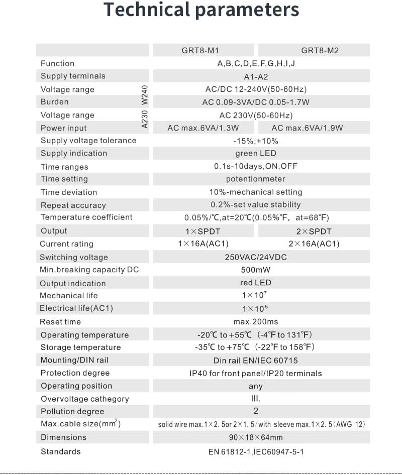
Figure 3: Technical specifications table comparing GRT8-M1 and GRT8-M2 models.
| Parameter | Value (GRT8-M1) |
|---|---|
| Function | A, B, C, D, E, F, G, H, I, J |
| Supply terminals | A1-A2 |
| Voltage range | AC230V (50-60Hz) |
| Burden | AC 0.09-3VA |
| Power input | AC max.6VA/1.3W |
| Supply voltage tolerance | -15%; +10% |
| Supply indication | green LED |
| Time ranges | 0.1s-10days, ON, OFF |
| Time setting | potentiometer |
| Time deviation | 10%-mechanical setting |
| Repeat accuracy | 0.2%-set value stability |
| Temperature coefficient | 0.05%/°C, at 20°C |
| Output | 1×SPDT |
| Current rating | 1×16A (AC1) |
| Switching voltage | 250VAC/24VDC |
| Min.breaking capacity DC | 500mW |
| Output indication | red LED |
| Mechanical life | 1×10⁷ |
| Electrical life (AC1) | 1×10⁵ |
| Reset time | max.200ms |
| Operating temperature | -20°C to +55°C |
| Storage temperature | -35°C to +75°C |
| Mounting/DIN rail | DIN rail EN/IEC 60715 |
| Protection degree | IP40 for front panel/IP20 terminals |
| Operating position | any |
| Overvoltage category | III. |
| Pollution degree | 2 |
| Max.cable size (mm²) | solid wire max.1×2.5 or 2×1.5 with sleeve max.1×2.5 (AWG 12) |
| Dimensions | 90×18×64mm |
| Standards | EN 61812-1, IEC60947-5-1 |
3. Installation and Wiring
The GRT8-M1 relay is designed for DIN rail mounting. Ensure all power is disconnected before installation or wiring.
3.1 Terminal Connections
- A1, A2: Power Supply Terminals (AC230V)
- S: Trigger Terminal (Control Input)
- 15: Common Contact
- 16: Normally Closed (NC) Contact
- 18: Normally Open (NO) Contact
3.2 Wiring Diagrams
Refer to the following diagrams for typical wiring configurations. Always consult local electrical codes and standards.

Figure 4: Internal wiring schematics for GRT8-M1 (1 SPDT output) and GRT8-M2 (2 SPDT outputs).

Figure 5: Example wiring diagram for function 'E' (Off Delay with S Break) controlling a lamp. L and N represent Live and Neutral connections. Signal is connected to terminal S.
Wiring Example for E Function:
- The relay is powered up.
- When the trigger 'S' is not connected, the bulb will not light.
- When 'S' and A1 are connected, the bulb will turn on.
- When 'S' is off, the relay delays for the set time, then the bulb will turn off.
- Terminal 15-18 is Normally Open (NO), 15-16 is Normally Closed (NC).
4. Operation and Settings
The GRT8-M1 features three rotary switches for setting time range, time percentage, and function mode.

Figure 6: Illustration of the three rotary knobs for Time Range, Time Percentage, and Function selection.
4.1 Time Range Setting (Knob 1)
The top knob (labeled 1) selects the time range. Available ranges are 0.1s, 1s, 10s, 1m, 10m, 1h, 10h, 1d, 10d, ON, OFF.
- 0.1s - 10 days: Adjustable time delay.
- ON: Output is permanently ON.
- OFF: Output is permanently OFF.
4.2 Time Percentage Setting (Knob 2)
The middle knob (labeled 2) adjusts the time within the selected range from 10% to 100%.
Example: If Time Range is set to "10m" and Time Percentage is set to "50%", the actual time delay will be 5 minutes.
4.3 Function Selection (Knob 3)
The bottom knob (labeled 3) selects one of the 10 delay functions (A-J).

Figure 7: Overview of the 10 delay modes, categorized by control method.
10 Delay Functions:
- Controlled by Power Supply Voltage:
- A: On Delay (Power on)
- B: Interval (Power on)
- C: Repeat Cycle (Starting off)
- D: Repeat Cycle (Starting on)
- E: Off Delay (S Break)
- Controlled by Control Input (S Terminal):
- F: Single Shot (Single Shot Trailing Edge)
- G: Non-Retriggerable
- H: On/Off Delay
- I: Latching relay
- J: Pulse generator
5. Maintenance
The GEYA GRT8-M1 time relay is designed for reliable, long-term operation with minimal maintenance. Follow these guidelines:
- Cleaning: Keep the device clean and free from dust and debris. Use a dry, soft cloth for cleaning. Do not use abrasive cleaners or solvents.
- Inspection: Periodically inspect wiring connections to ensure they are secure. Check for any signs of overheating or damage to the casing.
- Environment: Ensure the operating environment remains within the specified temperature and humidity ranges to prevent malfunction.
- No User Serviceable Parts: The device contains no user-serviceable parts. Do not attempt to open or repair the unit, as this will void the warranty and may pose a safety risk.
6. Troubleshooting
If you encounter issues with your GRT8-M1 time relay, consider the following common troubleshooting steps:
- No Power Indication (Green LED Off):
- Check the power supply voltage at terminals A1 and A2. Ensure it matches the specified AC230V.
- Verify all power connections are secure and correctly wired.
- Check for tripped circuit breakers or blown fuses in the power circuit.
- Output Not Switching (Red LED Off/Incorrect):
- Confirm the selected function (Knob 3) and time range/percentage (Knobs 1 & 2) are appropriate for your application.
- If using a control input (S terminal), ensure the trigger signal is correctly applied and within specifications.
- Verify the load connected to terminals 15, 16, 18 is correctly wired and not exceeding the relay's current rating (16A).
- Check the load itself (e.g., bulb, motor) to ensure it is functional.
- Incorrect Timing:
- Re-check the Time Range (Knob 1) and Time Percentage (Knob 2) settings.
- Ensure the selected function (Knob 3) corresponds to the desired timing behavior.
- Intermittent Operation:
- Inspect all wiring for loose connections or damaged insulation.
- Ensure the operating environment is stable and free from excessive electrical noise or temperature fluctuations.
If the problem persists after performing these checks, contact qualified personnel or the manufacturer for assistance. Do not attempt to repair the device yourself.
7. Safety Information
Please read and understand all safety instructions before installing or operating this device. Failure to follow these instructions may result in electrical shock, fire, or serious injury.
- Qualified Personnel: Installation and wiring must be performed by qualified electrical personnel in accordance with all national and local electrical codes.
- Disconnect Power: Always disconnect power to the circuit before installing, wiring, or performing any maintenance on the relay.
- Voltage Rating: Ensure the supply voltage matches the relay's specified voltage (AC230V).
- Current Rating: Do not exceed the maximum current rating of the relay (16A).
- Environment: Install the device in a dry, well-ventilated area, free from corrosive gases, excessive dust, and extreme temperatures.
- Grounding: Ensure proper grounding where applicable.
- Protection: Use appropriate overcurrent protection (e.g., circuit breakers) in the circuit.
8. Warranty and Support
For warranty information and technical support, please refer to the official GEYA website or contact your local distributor. Keep your purchase receipt as proof of purchase.
Manufacturer: ZHEJIANG GEYA ELECTRICAL CO.,LTD
Contact: Refer to GEYA Store on Amazon for further contact details or product information.


