1. Introduction
The CNCTOPBAOS DDCS Expert is a 5-axis motion controller designed for both open and closed-loop stepper and servo systems. It features a 7-inch full-color LCD display and offers a maximum output pulse frequency of 1MHz per axis. This controller allows users to customize functional keys and supports various spindle modes, including straight, gantry, and disk-type tool magazines. Built on an ARM+FPGA design framework, it ensures reliable control and user-friendly operation with its Linux-based internal operating system. The DDCS Expert functions as a standalone system, eliminating the need for an external computer, and is suitable for a wide range of CNC machinery such as lathes, routers, pick-and-place machines, milling machines, and engravers.

Figure 1.1: Front view of the CNCTOPBAOS DDCS Expert CNC Controller, showing the display and control panel.
2. Product Features
- Axis Control: Maximum 5 axes with 1MHz output frequency per axis. Supports 2-4 axis linear interpolation and any 2-axis circular interpolation.
- Display & Interface: 7-inch full-color LCD screen with 1024x600 resolution and 40 operation keys.
- I/O Capabilities: 24 photoelectric isolated digital inputs and 21 photoelectric isolated digital outputs.
- Spindle Control: Analog 0-10V spindle control, with PWM output support. Supports multi-speed (3 lines, 8 speeds) and servo spindle output.
- Tool Management: Supports multiple spindle modes including straight, gantry, and disk-type tool magazines.
- Probing: Compatible with both floating and fixed probes.
- Compensation: Features backlash compensation for direction gap, radius gap, and length.
- Interpolation Algorithms: Includes S-type, circular hard, and circular soft algorithms.
- Language Support: Available in Chinese and English.
- Alarm System: Provides software alarms for program errors, operation errors, overtravel, and driver issues.
- Connectivity: Ethernet support for file sharing and online machining of remote files.
- G-code Compatibility: Compatible with standard G-code and popular CAD/CAM software such as ArtCam, MasterCam, ProE, JDSoft SurfMill, Aspire, and Fusion 360.
- Advanced Processing: Path preview before machining, high-speed machining in continuous Polyline segments with automatic algorithm selection.
- File Handling: Supports unlimited file sizes for machining.
- Recovery Functions: Pause breakpoint resume, power cut recovery, and ability to start from a specific line.
- Security: Time-lock function and 4 levels of operation rights (visitor, operator, admin, super admin).
- Operational Modes: Supports 'Try cutting' (handwheel guiding) and 'Single-stage processing mode'.
- Homing: Function to return to the original point.
- Power Supply: Requires 24VDC, minimum 0.5A.
- Unit System: Supports both millimeters (default) and inches (set via G20 code).
- Slave Function: X-axis or Y-axis can be slaved to the A-axis.
3. Package Contents
Upon unpacking, please verify that all items listed below are present and in good condition:
- 1 x CNCTOPBAOS 5 Axis DDCS-EXPERT Offline Stand-alone CNC Controller
- 1 x 4GB USB Flash Drive
- 1 x USB Extension Cable
- 1 x Digital User Manual (PDF format, available for download or via message center)
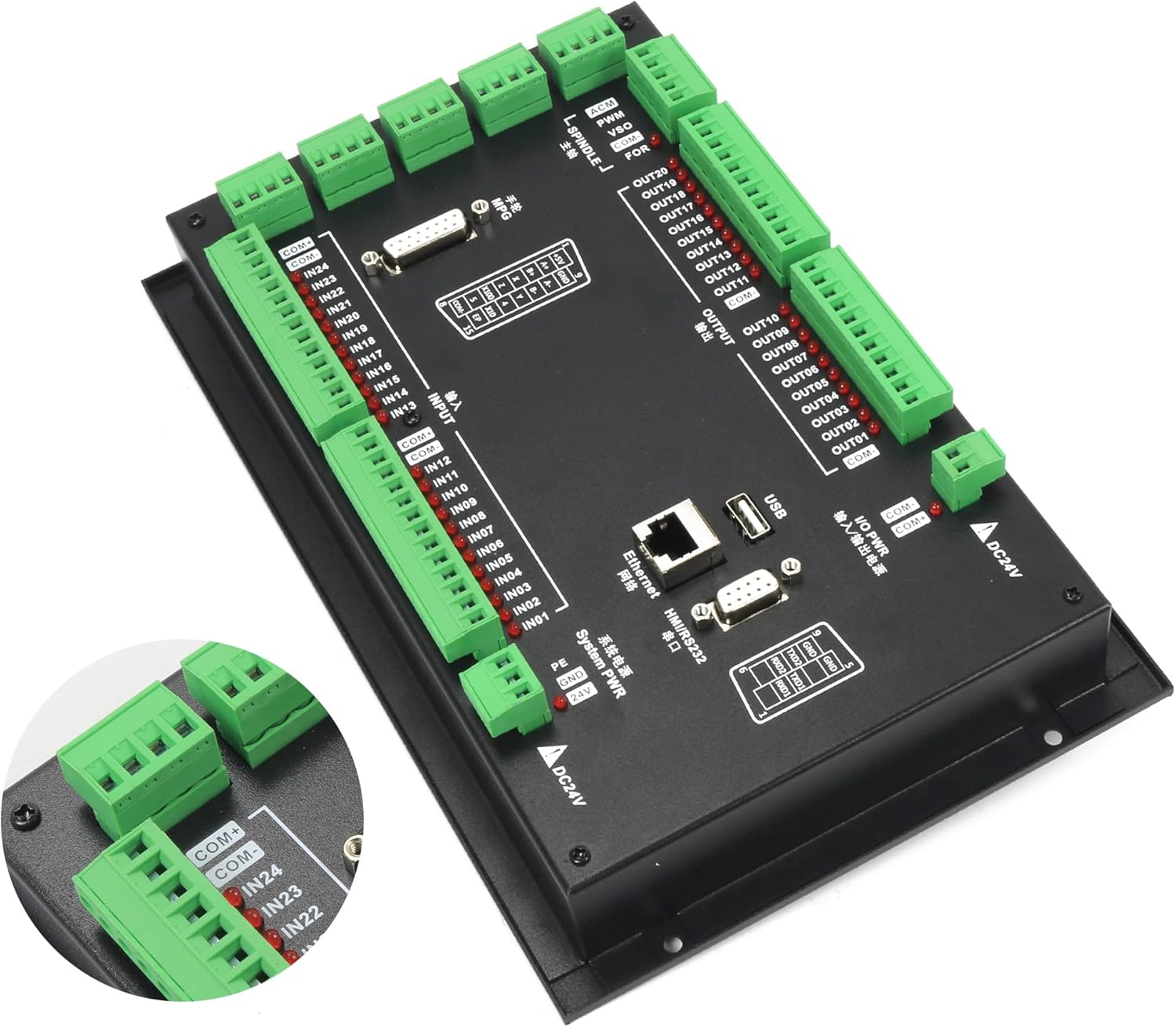
Figure 3.1: The DDCS Expert controller along with the USB flash drive and USB extension cable.
4. Setup and Installation
4.1 Physical Dimensions
The DDCS Expert controller is designed for integration into control boxes or cabinets. The following dimensions are provided for mounting purposes:
- Front Panel Dimensions: 268mm (width) x 172.5mm (height) x 5.2mm (thickness)
- Main Body Dimensions: 268mm (width) x 172.5mm (height) x 70mm (depth)
- Mounting Hole Cutout: 258.4mm (width) x 109mm (height)

Figure 4.1: Dimensional drawing of the DDCS Expert controller (Unit: mm).
4.2 Wiring Overview
The controller features various ports for driver signals, spindle control, input, output, and power. Careful attention to wiring is crucial for proper operation and safety.

Figure 4.2: Comprehensive wiring diagram showing connections for various components.
4.3 Power Supply Connections
The controller requires a 24VDC power supply. It is recommended to use an EMI filter for stable operation.

Figure 4.3: Power supply wiring with recommended EMI filter for system and I/O power.
4.4 Stepper/Servo Driver Connections
Connect your stepper or servo drivers to the dedicated driver signal output ports. Ensure correct polarity for pulse and direction signals.

Figure 4.4: Example wiring for a stepper motor and its driver to the controller.
4.5 Input Device Connections
The controller supports various input devices such as proximity switches, mechanical switches, and probes.

Figure 4.5: Wiring for input devices including proximity switches, mechanical switches, and a probe.
4.6 External Button Connections
External START, PAUSE, and RESET buttons can be wired to the input ports for convenient operation.

Figure 4.6: Wiring diagram for external control buttons.
4.7 Tool Setter/Probe Wiring
A tool setter or probe can be connected to the input ports for automated tool length measurement or workpiece referencing.

Figure 4.7: Wiring for a tool setter or probe.
4.8 MPG (Manual Pulse Generator) Wiring
An MPG can be connected for precise manual control of axes. Refer to the pinout diagram for correct connections.

Figure 4.8: MPG wiring diagram and pin definitions.
4.9 Spindle Control Wiring
The controller supports various spindle control methods, including direct motor connection and inverter-based control.

Figure 4.9: Spindle motor wiring using an inverter for speed control.

Figure 4.10: Spindle motor wiring with direct speed control connections.
4.10 Output Control Wiring
The output ports can be used to control auxiliary devices such as cooling systems or vacuum pumps via solid-state relays.

Figure 4.11: Output wiring for controlling cooling and vacuum functions.
5. Operation
5.1 User Interface Overview
The DDCS Expert features an intuitive user interface with a 7-inch display and 40 operational keys. The main screen displays real-time machine status, coordinates, and operational parameters.

Figure 5.1: Close-up view of the controller's front panel, highlighting key interface elements.
5.2 Key Abbreviations and Modes
Understanding the abbreviations used on the display and in the manual is essential for effective operation:
- FRO: Feed Rate Override - Adjusts the current feed rate percentage.
- SRO: Spindle Rate Override - Adjusts the current spindle speed percentage.
- SJR: Jog Speed Setting - Configures the speed for manual jogging.
- F: Feed rate - Unit is typically mm/min.
- S: Spindle Speed - Unit is revolutions per minute (rev/min).
- X, Z, A: Coordinate codes for the respective axes.
- BUSY: Indicates the system is currently executing a task. FRO and SRO can still be adjusted.
- READY: The controller is idle and ready for any operation.
- RESET: The controller is in an 'OFF' state; no operations can be performed.
- CONT: Continuous mode - Allows manual jogging of each axis using arrow keys.
- Step: Manual Step Mode - Each axis can be jogged in defined incremental steps.
- MPG: MPG mode - Enables machine operation using a Manual Pulse Generator.
5.3 Basic Operation Flow
- Power On: Ensure all connections are secure and apply 24VDC power.
- System Initialization: Wait for the controller to boot up and display the READY status.
- Load Program: Use the USB flash drive or Ethernet connection to load your G-code program.
- Set Workpiece Origin: Manually jog axes or use probing functions to set the workpiece zero point.
- Tool Setting: Perform tool length measurement if required.
- Start Machining: Initiate the program. Monitor progress and adjust overrides (FRO, SRO) as needed.
- Emergency Stop: In case of any issue, press the emergency stop button immediately.
6. Maintenance
Regular maintenance ensures the longevity and optimal performance of your DDCS Expert controller.
- Cleaning: Keep the controller's display and buttons clean using a soft, dry cloth. Avoid abrasive cleaners or solvents.
- Connection Checks: Periodically inspect all wiring connections for tightness and signs of wear or corrosion. Loose connections can lead to erratic behavior.
- Environmental Control: Operate the controller within its specified temperature and humidity ranges. Protect it from excessive dust, moisture, and direct sunlight.
- Software Updates: Check the manufacturer's website for any available firmware updates to ensure you have the latest features and bug fixes.
- Backup Settings: Regularly back up your controller's configuration parameters to the USB flash drive.
7. Troubleshooting
This section provides general guidance for common issues. For detailed troubleshooting, refer to the comprehensive digital user manual.
- Controller Not Powering On: Verify the 24VDC power supply connection and ensure it is providing adequate current (minimum 0.5A). Check for any blown fuses in the power circuit.
- Axes Not Moving: Confirm that drivers are powered and enabled. Check wiring for pulse and direction signals. Ensure the controller is not in RESET mode and that no emergency stop is active.
- Program Errors: Review the G-code for syntax errors. Check for overtravel alarms or limit switch activations.
- Inaccurate Movement: Verify motor tuning parameters and backlash compensation settings. Ensure mechanical components of the CNC machine are functioning correctly.
- Communication Issues: If using Ethernet, check network cable connections and IP settings. For USB, ensure the drive is properly formatted and recognized.
If issues persist, consult the full user manual or contact CNCTOPBAOS technical support.
8. Specifications
| Feature | Specification |
|---|---|
| Brand | CNCTOPBAOS |
| Model Number | 5 Axis DDCSE Controller |
| Display Type | LCD |
| Voltage | 24 Volts DC |
| Material | Plastic |
| Item Weight | 3.52 pounds (1.6 Kilograms) |
| Package Dimensions | 12.17 x 8.54 x 4.25 inches |
| Manufacturer | Changzhou Rattm Motor Co.,Ltd |
9. Warranty and Support
For warranty information and technical support, please refer to the documentation provided with your purchase or contact CNCTOPBAOS directly through their official channels. Ensure you have your product model number and purchase details available when seeking support.
You can visit the CNCTOPBAOS Store for additional product information and contact options.


