
1. Introduction
This manual provides essential information for the proper installation, operation, and maintenance of the HOCHIKI HSC-4R/12-4-Wire 6-inch Relay Base. It is crucial to read and understand all instructions before proceeding with any procedures. This device is designed for use in fire detection systems and must be installed by qualified personnel in accordance with all local and national codes and standards.
Safety Warning: Improper installation or maintenance can lead to system malfunction, property damage, serious injury, or death. Always disconnect power before servicing.
2. Product Overview
The HOCHIKI HSC-4R/12-4-Wire Relay Base is a specialized accessory designed to integrate with compatible HOCHIKI fire detectors, specifically the HD-3 or HD-5 models. This 6-inch base provides relay contacts that activate upon detector alarm, allowing for control of auxiliary devices such as door holders, fan shutdowns, or annunciators within a fire alarm system. It operates on a 12 Vdc coil voltage and features a robust screw-type connector system for secure wiring.
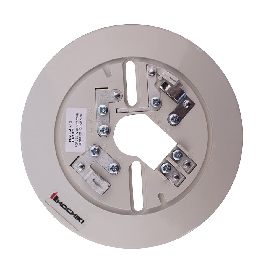
This image displays the HOCHIKI HSC-4R/12-4-Wire 6-inch Relay Base. The base is circular and light gray, featuring multiple screw terminals for wiring connections. Visible labels include 'HSC-4R12', 'H087', 'FOR USE WITH DETECTOR IDENTIFIER HD-3 OR HD-5', and the 'HOCHIKI' logo. Terminal markings like L1, L2, S1, S2, L3, L4, H1, H2 are also present, indicating various connection points for power, signal, and relay outputs.
3. Setup and Installation
Installation of the HSC-4R/12-4-Wire Relay Base must be performed by a certified technician in compliance with NFPA 72, local building codes, and the manufacturer's instructions.
3.1 Mounting
- The relay base is designed for DIN Rail Mount installation. Ensure the mounting surface is stable and free from vibrations.
- Securely attach the base to the DIN rail using appropriate fasteners.
3.2 Wiring
The HSC-4R/12-4-Wire base requires a 4-wire connection and operates on a 12 Vdc coil voltage. Refer to the system wiring diagram provided by the fire alarm control panel manufacturer for specific connections. The base features screw-type terminals for reliable connections.
Typical terminal designations include:
- L1, L2: Power input for the detector.
- S1, S2: Signal lines for communication with the fire alarm control panel.
- L3, L4: Relay contact terminals (e.g., Normally Open/Normally Closed).
- H1, H2: Auxiliary connections, potentially for remote indicator or additional power.
Ensure all wiring is correctly polarized and securely fastened to prevent intermittent operation or system faults. Verify all connections before applying power.
3.3 Detector Installation
Once the base is mounted and wired, align the compatible HOCHIKI detector (HD-3 or HD-5) with the base and twist clockwise until it locks into place. Ensure the detector is firmly seated.
4. Operating Instructions
The HOCHIKI HSC-4R/12-4-Wire Relay Base functions passively in conjunction with its connected detector. When the detector senses an alarm condition (e.g., smoke, heat), it signals the fire alarm control panel, and simultaneously, the relay within the base will activate. This activation changes the state of the relay contacts (L3, L4), which can then be used to trigger external devices.
- Normal Operation: The relay contacts remain in their standby state (e.g., Normally Open contacts are open, Normally Closed contacts are closed).
- Alarm Condition: Upon an alarm from the connected detector, the relay coil is energized, causing the contacts to switch state. This state change persists as long as the detector is in alarm and power is supplied.
- Reset: The relay will return to its normal state once the fire alarm control panel is reset and the detector clears its alarm condition.
5. Maintenance
Regular maintenance is essential to ensure the continued reliable operation of the HSC-4R/12-4-Wire Relay Base and the overall fire alarm system.
- Periodic Inspection: Visually inspect the base and its wiring connections annually for any signs of damage, corrosion, or loose terminals.
- Cleaning: If dust or debris accumulates on the base, gently clean it with a soft, dry cloth. Do not use abrasive cleaners or solvents.
- System Testing: Follow the fire alarm system manufacturer's guidelines for periodic testing of detectors and associated relay functions. This typically involves activating the detector to verify relay operation.
- Professional Servicing: All maintenance and testing should be conducted by qualified fire alarm technicians.
6. Troubleshooting
If the relay base or connected detector is not functioning as expected, consider the following troubleshooting steps. Always ensure power is disconnected before inspecting wiring.
- Relay Not Activating:
- Verify the connected detector is in an alarm state.
- Check for proper 12 Vdc power supply to the base.
- Inspect all wiring connections (L1, L2, S1, S2) for looseness or incorrect polarity.
- Ensure the detector is correctly seated and locked onto the base.
- Intermittent Operation:
- Check for loose wiring connections at all terminals.
- Inspect for environmental factors such as excessive vibration or moisture.
- System Fault:
- Consult the fire alarm control panel manual for specific fault codes.
- Verify continuity of all wiring.
If issues persist after basic troubleshooting, contact a qualified fire alarm technician for further assistance.
7. Specifications
| Brand | HOCHIKI |
| Model | HSC-4R/12-4-Wire |
| Mounting Type | DIN Rail Mount |
| Connector Type | Screw |
| Coil Voltage | 12 Volts DC |
| Compatibility | For use with HOCHIKI Detector Identifier HD-3 or HD-5 |
| First Available | March 1, 2022 |
8. Warranty and Support
For warranty information, please refer to the official HOCHIKI website or contact your authorized HOCHIKI distributor. Warranty terms and conditions may vary based on region and purchase date.
For technical support or further assistance, please contact your local HOCHIKI representative or the dealer from whom the product was purchased. Ensure you have the model number (HSC-4R/12-4-Wire) and any relevant system details available when seeking support.