1. Introduction
The DUMBORC X6FG is a 6-channel 2.4GHz RC receiver featuring an integrated gyroscope for enhanced vehicle stability. This receiver supports two working modes: Normal mode and Gyro mode, allowing for precise control and correction of vehicle direction to prevent deviation and skidding. It is designed for easy binding and offers stable long-distance control with FHSS spread spectrum technology, ensuring reliable operation with a 400m control distance and 12ms fast response speed. The X6FG also includes a reverse polarity protection circuit to prevent damage and supports 4.8-10V DC high voltage servos.

Figure 1: DUMBORC X6FG 6-Channel RC Receiver
2. Product Overview
The DUMBORC X6FG receiver is a compact unit designed for various RC applications. It features six channels for connecting servos and other components, a binding button, and an LED indicator for mode status.

Figure 2: DUMBORC X6FG Receiver with labeled ports (CH1-CH6, VCC, GND, Signal, Antenna, Binding Button, Mode LED Indicator).
Key Features:
- Built-in Gyro: Provides stability and directional correction.
- 6 Channels: Supports multiple functions for RC models.
- 2.4GHz FHSS: Ensures stable and interference-free communication.
- 4.8-10V DC: Supports high voltage servos.
- Reverse Polarity Protection: Safeguards the receiver from incorrect power connections.
3. Setup
3.1. Receiver Connection Diagram
Proper connection of the receiver to your RC model's components is crucial for correct operation. Ensure all connections are secure and correctly oriented.

Figure 3: Diagram showing connections from the receiver to the battery, ESC, motor, and servo. Channel 1 is typically for steering, and Channel 2 for throttle.
3.2. Binding Instructions
The receiver needs to be bound to your DUMBORC transmitter (X6, X4, X5, X6PM-350 series) for the first time. Follow these steps:
- Ensure the transmitter and receiver are approximately 30-50 cm apart.
- Power on the transmitter.
- Power on the X6FG receiver.
- Locate the tiny binding button on the receiver (next to the antenna).
- Use a small, non-conductive tool (like a pen tip) to press and hold the binding button on the receiver.
- The green LED indicator on the receiver will flash rapidly, indicating it's in binding mode.
- Release the binding button once the LED starts flashing.
- The LED will turn solid green, indicating successful binding.

Figure 4: Visual guide for the binding process, showing the location of the binding button and the LED indicator.
Video 1: Demonstrates the binding method for the DUMBORC X6FG receiver with an X6 transmitter. It shows powering on the transmitter and receiver, then pressing the binding button until the LED turns solid green.
4. Operating Instructions
4.1. Normal Mode and Gyro Mode
The X6FG receiver operates in two modes: Normal Mode (gyro off) and Gyro Mode (gyro on). The LED indicator on the receiver will show green for Normal Mode and red for Gyro Mode.

Figure 5: LED indicators for Normal Mode (Green) and Gyro Mode (Red) on the DUMBORC X6FG receiver.
4.2. Switching to Gyro Mode
To switch between Normal Mode and Gyro Mode:
- Quickly press the binding button three times within one second.
- The LED indicator will change from green (Normal Mode) to red (Gyro Mode).

Figure 6: Illustration showing how to switch between Normal (Green LED) and Gyro Mode (Red LED) by pressing the binding button three times.

Figure 7: Diagram illustrating the difference in vehicle stability and directional correction with and without the gyro function enabled.
Video 2: Demonstrates the Gyro Mode function of the DUMBORC X6FG 6CH Receiver, showing how to activate it and its effect on vehicle stability.
4.3. Gyro Sensitivity Adjustment
Gyro sensitivity is typically controlled by Channel 6 on compatible DUMBORC transmitters. Turn the knob for Channel 6 to adjust the sensitivity. Turning clockwise increases sensitivity, and counter-clockwise decreases it.
4.4. Auxiliary Channel Usage
Auxiliary Channels 3 to 6 can be used to control additional devices such as lights or other accessories. These typically require connection to a switch relay board (not included).

Figure 8: Example of auxiliary channel usage, showing channels 3-6 on a transmitter controlling LED lights via a switch relay board.
5. Troubleshooting
5.1. Throttle or Steering Not Working
If your throttle or steering is not responding, ensure the 'sub-trim of Throttle' on your transmitter is set to zero. An incorrect sub-trim setting can prevent the Electronic Speed Controller (ESC) from recognizing the throttle input.
- Locate the sub-trim adjustment for throttle on your DUMBORC transmitter.
- Adjust the sub-trim to the '0' position.
- If the issue persists, reset the transmitter, check the ESC, and calibrate it to ensure it is a two-way ESC with the correct working mode.
Video 3: Explains common reasons why the throttle or steering might not work and how to resolve them, focusing on adjusting the throttle sub-trim.
5.2. Gyro Direction Reversed
If the gyro correction is working in the opposite direction (e.g., turning left when the car drifts right), you can reverse the gyro direction:
- Ensure the receiver is in Gyro Mode (red LED).
- Quickly press the binding button twice within one second.
- This action will reverse the gyro's correction direction.
6. Specifications
| Feature | Specification |
|---|---|
| Model Number | X6FG |
| Channels | 6 |
| Frequency | 2.4GHz |
| Operating Voltage | 4.8-10V DC |
| Control Distance | Up to 400 meters |
| Response Speed | 12ms |
| Dimensions | 0.79 x 0.51 x 1.38 inches |
| Weight | 0.317 ounces |
| Manufacturer | Eighteenup |

Figure 9: Physical dimensions of the DUMBORC X6FG receiver.
7. Safety Information
Always operate your RC equipment responsibly. Observe the following safety guidelines:
- Ensure all connections are correct and secure before powering on.
- Never operate RC vehicles in crowded areas or near people, pets, or property.
- Keep hands and loose clothing away from moving parts.
- Always turn on the transmitter first, then the receiver. When powering off, turn off the receiver first, then the transmitter.
- Store the receiver and other RC components in a dry, safe place away from extreme temperatures.
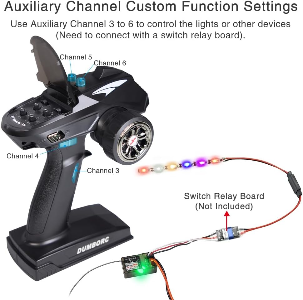
Figure 10: Illustration of the reverse polarity protection circuit, showing correct and incorrect cable connections to prevent receiver damage.
8. Warranty and Support
For warranty information, technical support, or service inquiries, please refer to the contact details provided with your product packaging or visit the official ATA HOBBY website. Keep your purchase receipt as proof of purchase.


