1. Introduction
This manual provides detailed instructions for the installation, operation, and maintenance of your DEWENWILS Wireless Light Switch and Receiver Kit. This kit offers a convenient solution for controlling lighting fixtures without the need for complex in-wall wiring, allowing for flexible placement of the switch.
2. Safety Information
- Always cut off power at the circuit breaker before performing any electrical work.
- Ensure all wiring connections are secure and comply with local electrical codes.
- Do not exceed the maximum load ratings of 10A/1200W (Tungsten), 600W (Fluorescent), or 200W (LED).
- This product is designed for indoor use. Avoid exposure to moisture or extreme temperatures.
- If you are unsure about any part of the installation, consult a qualified electrician.
3. Package Contents
The DEWENWILS Wireless Light Switch and Receiver Kit includes the following components:
- 1 x Wireless Wall Switch (Transmitter)
- 2 x Receiver Modules
- 1 x 12V (23A) Alkaline Battery (pre-installed in switch)
- Mounting Screws and Adhesive Tape for Switch

Image: The DEWENWILS Wireless Light Switch and Receiver Kit, showing one wireless wall switch and two receiver modules.
4. Specifications
| Feature | Specification |
|---|---|
| Brand | DEWENWILS |
| Model Number | HRLS12E |
| Current Rating | 10 Amps |
| Operating Voltage | 125 Volts |
| Maximum Power (Tungsten) | 1000 Watts |
| Maximum Power (Fluorescent) | 600 Watts |
| Maximum Power (LED) | 200 Watts |
| Control Method | Remote (RF) |
| RF Range | Up to 100 feet (open areas) |
| Connectivity Protocol | RF |
| IP Rating | IP54 |
| Battery Type (Switch) | 1 x 12V (23A) Alkaline (included) |
| Receiver Dimensions (L x W x H) | 2.14 x 1.46 x 0.92 inches (approx.) |
5. Setup and Installation
5.1. Receiver Wiring
The receiver module connects between your power source and the lighting fixture. A neutral wire is required for installation. Ensure power is OFF at the circuit breaker before proceeding.
- Turn off the main power supply to the circuit at the breaker.
- Connect the Red wire from the receiver to the Live (L) input wire from your power source.
- Connect the Blue wire from the receiver to the Neutral (N) input wire from your power source.
- Connect the Black wire from the receiver to the Live (L) output wire of your lighting fixture.
- Connect the White wire from the receiver to the Neutral (N) output wire of your lighting fixture.
- Ensure the ground wire (G) from your power source is connected to the ground wire of your lighting fixture as normal.
- The compact receiver is designed to fit into various electrical boxes such as rose/canopy, junction boxes, or switch boxes.

Image: A wiring diagram illustrating how to connect the receiver between the power input and a light fixture. It also shows the compact dimensions of the receiver, indicating it fits into standard electrical boxes like rose/canopies, junction boxes, and switch boxes.
5.2. Wireless Switch Mounting
The wireless switch can be mounted on a wall or used as a portable remote.
- Remove the back plate from the wireless switch.
- Choose a desired location for the switch. You can use the provided screws to mount the back plate to the wall or use the adhesive tape for a non-permanent solution.
- Ensure the battery insulation tab is removed from the switch to activate the pre-installed 12V (23A) alkaline battery.
- Snap the wireless switch onto the mounted back plate.

Image: A visual guide showing the steps to install the wireless switch, including removing the back plate, using screws or adhesive for mounting, and snapping the switch into place. It also highlights the battery and insulation tab.

Image: A visual comparison showing a traditional wired switch for a ceiling fan versus the DEWENWILS wireless system, demonstrating how the wireless switch eliminates the need for new in-wall wiring.
6. Operating Instructions
6.1. Basic Operation
Once the receiver is wired and the switch is powered, you can control your lighting fixture:
- Press the "ON" button on the wireless switch to turn the connected light(s) ON.
- Press the "OFF" button on the wireless switch to turn the connected light(s) OFF.
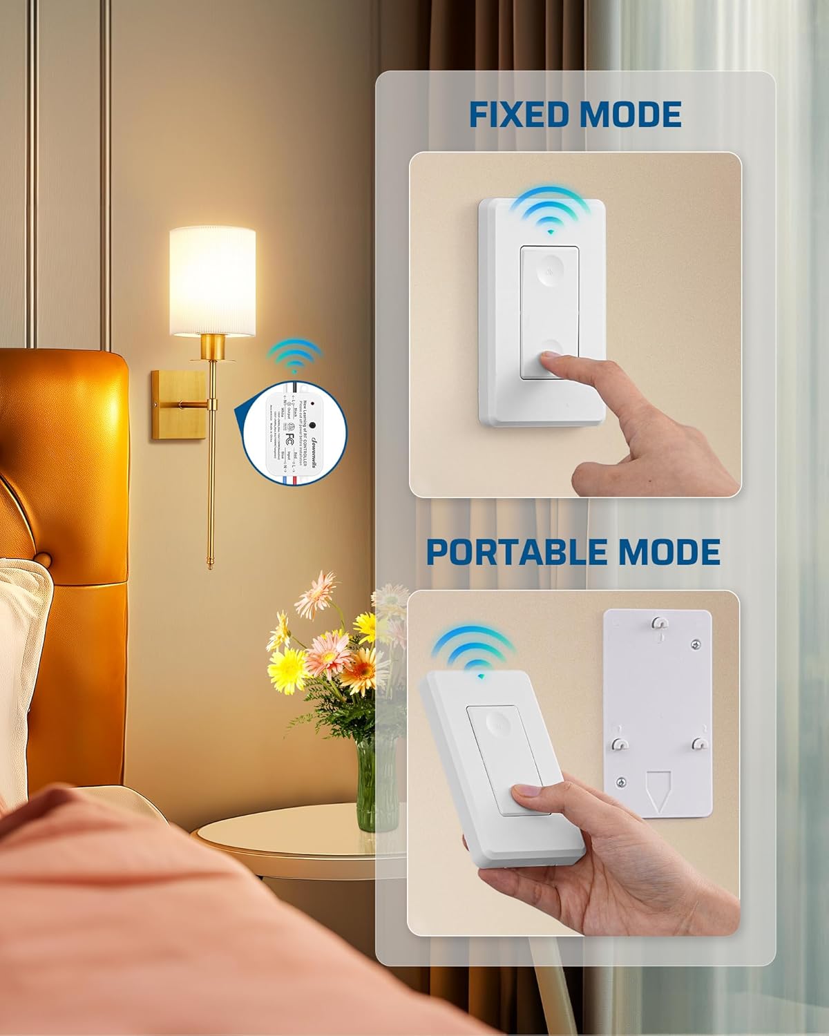
Image: The wireless switch is shown in two configurations: fixed to a wall plate and used as a portable remote, demonstrating its versatility.
6.2. RF Range and Interference
The system utilizes RF (Radio Frequency) technology, providing a range of up to 100 feet in open areas. The signal can pass through walls and doors without requiring a direct line of sight.

Image: A cross-section view of a house demonstrating the 100-foot RF range, showing the wireless switch controlling lights in different rooms and on different floors.
6.3. Programmable and Expandable Features
The DEWENWILS Wireless Light Switch Kit is designed for expandability:
- One Switch, Multiple Receivers: A single wireless switch can be paired to control multiple receiver modules, allowing one switch to control a group of lights.
- Multiple Switches, One Receiver: Multiple wireless switches can be paired to control a single receiver module, enabling 3-way or 4-way switch configurations without additional wiring.
- Additional DEWENWILS transmitters and receivers can be purchased separately to expand your system.

Image: A collage showing various home lighting applications, including ceiling lights, wall sconces, and pendant lamps, all compatible with the DEWENWILS wireless switch system.
Video: An official DEWENWILS video demonstrating the functionality and ease of use of the Wireless Light Switch and Receiver Kit in various home settings.
7. Maintenance
7.1. Battery Replacement (Wireless Switch)
The wireless switch is powered by a 12V (23A) alkaline battery. If the switch stops responding or the indicator light (if present) does not illuminate, the battery may need replacement.
- Carefully detach the wireless switch from its wall-mounted back plate or open the battery compartment if it's a portable unit.
- Remove the old 12V (23A) battery.
- Insert a new 12V (23A) alkaline battery, ensuring correct polarity.
- Reassemble the switch.
8. Troubleshooting
| Problem | Possible Cause | Solution |
|---|---|---|
| Light does not turn ON/OFF. | No power to receiver, incorrect wiring, dead switch battery, switch not paired. | Check circuit breaker. Verify wiring connections. Replace switch battery. Re-pair switch and receiver (refer to programming instructions, if applicable). |
| Reduced RF range or intermittent control. | Obstructions (thick walls, metal objects), interference from other RF devices, low switch battery. | Relocate the switch or receiver to minimize obstructions. Ensure no other strong RF sources are nearby. Replace switch battery. |
| Lights flicker or do not operate correctly. | Overload on the receiver, incompatible bulb type, faulty receiver. | Ensure total wattage does not exceed receiver's maximum load. Verify bulb compatibility (Tungsten, Fluorescent, LED). Contact support if receiver is suspected faulty. |
9. Warranty and Support
DEWENWILS products typically come with a standard manufacturer's warranty. For specific warranty details, technical support, or to purchase additional components, please refer to the product packaging or visit the official DEWENWILS website. Contact information for customer service is usually provided with the product documentation.


