
1. Introduction
This manual provides detailed instructions for the installation, operation, and maintenance of the xcluma BE-002600 Brushless Motor Intelligent Dual Mode Controller. This controller is designed for electric vehicles such as bikes, scooters, and e-rickshaws, supporting both 36V and 48V systems with a rated power of 350W. Please read this manual thoroughly before installation and use to ensure proper function and safety.
2. Safety Information
- Always disconnect the battery power before performing any installation or maintenance.
- Ensure all connections are secure and correctly wired to prevent damage to the controller or other components.
- Avoid exposing the controller to water, excessive moisture, or extreme temperatures.
- Do not attempt to open or modify the controller casing, as this will void the warranty and may cause malfunction.
- Consult a qualified technician if you are unsure about any installation steps.
3. Product Overview
The xcluma BE-002600 is a smart dual-mode controller featuring a robust aluminum casing for durability and heat dissipation. It is designed to efficiently manage power for brushless motors in various electric vehicle applications.

Image 1: Front view of the xcluma BE-002600 Brushless Motor Controller, showing its aluminum housing and multiple colored wiring harnesses.

Image 2: Side view of the xcluma BE-002600 Brushless Motor Controller, providing a clearer look at the wire entry point and connector types.
Key Features:
- Smart Dual Mode operation (Hall sensor and sensorless).
- Supports 36V and 48V battery systems.
- Rated power output of 350 Watts.
- Low voltage protection at 31V/41V ± 0.5V.
- Durable aluminum construction.
4. Setup and Installation
Careful wiring is essential for the correct operation of the controller. Refer to the wiring diagram below and the descriptions for each connection.
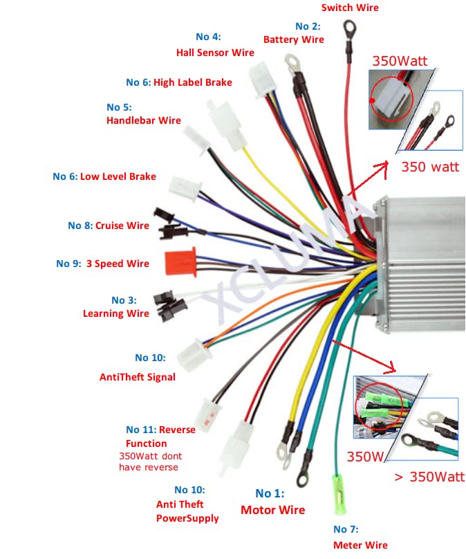
Image 3: Comprehensive wiring diagram for the xcluma BE-002600 Controller, illustrating each numbered wire and its corresponding function.
Wiring Connections:
- No 1: Motor Wire - Connect these three thick wires (typically green, yellow, blue) to the corresponding phase wires of your brushless motor.
- No 2: Battery Wire - Connect the thick red wire to the positive (+) terminal of your 36V/48V battery and the thick black wire to the negative (-) terminal. Ensure correct polarity.
- No 3: Learning Wire - These two wires are used for initial motor learning. Connect them together briefly during the first power-up to allow the controller to learn the motor's phase sequence. Disconnect after learning is complete.
- No 4: Hall Sensor Wire - Connect this multi-pin connector to the Hall sensor output of your brushless motor. This is crucial for Hall-sensor-based operation.
- No 5: Handlebar Wire (Throttle) - Connect this to your throttle assembly. This typically includes power, ground, and signal wires for speed control.
- No 6: High Level Brake & Low Level Brake - Connect these wires to your brake levers. The controller will cut power to the motor when brakes are applied.
- No 7: Meter Wire - Connect to your display or meter for speed, battery level, and other vehicle information.
- No 8: Cruise Wire - Connect these wires to enable or disable the cruise control function, if available on your vehicle.
- No 9: 3 Speed Wire - Connect these wires to a 3-speed switch to select between different speed modes (e.g., low, medium, high).
- No 10: Anti-Theft Signal & Anti-Theft Power Supply - These wires are for connecting an anti-theft alarm system. The signal wire receives input from the alarm, and the power supply provides power to the alarm module.
- No 11: Reverse Function - Note that for 350W controllers, the reverse function is typically not supported. Do not connect these wires if your motor is 350W.
- Switch Wire - This wire is typically used to turn the controller on/off, often connected to the vehicle's ignition switch.
After all connections are made, double-check them for correctness and security before applying power.
5. Operating Instructions
Once the controller is correctly installed and wired:
- Power On: Turn on the main power switch of your electric vehicle. The controller will initialize.
- Throttle Control: Gently twist the throttle to accelerate. The motor speed will correspond to the throttle position.
- Braking: Applying the brake levers will cut power to the motor, ensuring safe deceleration.
- Speed Modes: If a 3-speed switch is connected, use it to select your desired speed mode.
- Cruise Control: If connected, activate the cruise control function as per your vehicle's instructions.
6. Maintenance
The xcluma BE-002600 controller requires minimal maintenance. Follow these guidelines:
- Keep the controller clean and free from dust and debris.
- Regularly inspect all wiring connections for looseness or damage. Tighten or repair as necessary.
- Ensure adequate airflow around the controller to prevent overheating, especially during prolonged use.
- Avoid harsh impacts or vibrations that could damage internal components.
7. Troubleshooting
If you encounter issues with your controller, refer to the following common problems and solutions:
| Problem | Possible Cause | Solution |
|---|---|---|
| Motor not running | No power, loose connections, faulty throttle, motor or Hall sensor issue. | Check battery connection, main power switch, all wire connections. Test throttle. Check motor and Hall sensor wires. |
| Motor runs intermittently | Loose connections, intermittent Hall sensor signal, overheating. | Inspect all connections. Ensure controller has proper ventilation. |
| Motor makes unusual noise | Incorrect motor phase connection, Hall sensor issue, motor damage. | Verify motor phase wires (No 1) and Hall sensor wires (No 4) are correctly connected. Perform learning procedure again. |
| Controller gets hot | Overload, insufficient ventilation, short circuit. | Reduce load on the motor. Ensure controller is in a well-ventilated area. Check for any short circuits in the wiring. |
If problems persist after troubleshooting, contact customer support.
8. Specifications
| Feature | Specification |
|---|---|
| Model Number | BE-002600 |
| Item Type | Smart Dual Mode Electric Vehicle Controller |
| Material | Aluminium |
| Rated Voltage | 36V / 48V |
| Low Voltage Protection | 31V / 41V ± 0.5V |
| Rated Power | 350 Watt |
| Product Dimensions (LxWxH) | 7 x 10 x 7 cm |
| Item Weight | 150 g |
9. Warranty and Support
For warranty information or technical support, please contact the manufacturer or your retailer. Ensure you have your model number (BE-002600) and purchase details available when contacting support.
Manufacturer: Bytesware Electronics
Contact: ELECTROBOT CONTACT NO - 8447558113