
1. Introduction
This manual provides detailed instructions for setting up, operating, and maintaining your DORHEA ESP32 ESP-32S WiFi Development Board. The ESP32 is a powerful, low-cost, low-power system on a chip (SoC) series with integrated Wi-Fi and dual-mode Bluetooth. It is designed for mobile devices, wearable electronics, and Internet of Things (IoT) applications. This board is compatible with the Arduino IDE, making it accessible for both beginners and experienced developers.
2. Product Overview
2.1 Key Features
- Dual-core ESP-32 processor.
- Integrated 2.4GHz Wi-Fi and dual-mode Bluetooth.
- Ultra-low power consumption.
- Compact size for easy integration into various products.
- Compatible with Arduino IDE.
- Supports Lua programming, LWIP protocol, and FreeRTOS.
- Operates in three modes: Access Point (AP), Station (STA), and AP+STA.
- Features a low-power coprocessor for continuous monitoring.
2.2 Board Components
The DORHEA ESP32 ESP-32S WiFi Development Board includes the ESP-WROOM-32 module, a CP2102 USB-to-UART bridge for communication, and various GPIO pins for interfacing with external components. It also features 'BOOT' and 'EN' buttons for programming and resetting.
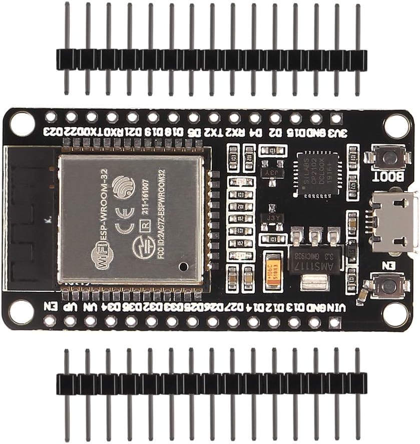
Figure 1: DORHEA ESP32 ESP-32S WiFi Development Board with included male headers. This image shows the top view of the board, highlighting the ESP-WROOM-32 module, USB port, and pin headers.

Figure 2: Front and back views of the ESP32 development board. The front displays the main components, while the back shows the 'ESP32 DEVKITV1' label.

Figure 3: Physical dimensions of the ESP32 development board, measuring approximately 52mm (2.04in) in length, 28mm (1.10in) in width, and 10mm (0.39in) in height with headers.
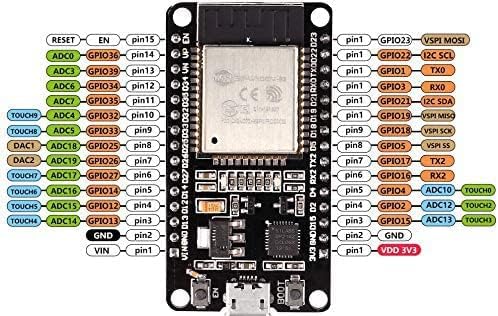
Figure 4: Detailed pinout diagram for the ESP32 development board, illustrating the various GPIOs, power pins (3V3, GND, VIN), and special function pins (ADC, TOUCH, DAC, TX, RX, I2C, SPI).
3. Setup Guide
3.1 Driver Installation (CP2102)
Before connecting your ESP32 board to your computer, you may need to install the CP2102 USB-to-UART bridge driver. This driver allows your computer to communicate with the ESP32 board via the USB port.
- Download the latest CP2102 driver for your operating system (Windows, macOS, Linux) from the official Silicon Labs website.
- Follow the installation instructions provided with the driver package.
- After installation, restart your computer if prompted.
3.2 Arduino IDE Setup
The ESP32 board can be programmed using the Arduino IDE. Follow these steps to prepare your IDE:
- Download and install the Arduino IDE from the official Arduino website.
- Open the Arduino IDE. Go to File > Preferences.
- In the 'Additional Boards Manager URLs' field, add the following URL:
https://raw.githubusercontent.com/espressif/arduino-esp32/gh-pages/package_esp32_index.json - Go to Tools > Board > Boards Manager.... Search for "ESP32" and install the "ESP32 by Espressif Systems" package.
- Once installed, select your specific ESP32 board (e.g., "ESP32 Dev Module") from Tools > Board > ESP32 Arduino.
3.3 Connecting the Board
Connect the ESP32 development board to your computer using a micro-USB cable. Ensure the cable is data-capable, as some cables are charge-only. The board should power on, indicated by a power LED (if present).
4. Operating Instructions
4.1 Uploading a Sketch
To upload your code (sketch) to the ESP32 board using the Arduino IDE:
- Open your sketch in the Arduino IDE.
- Select the correct board from Tools > Board > ESP32 Arduino.
- Select the correct COM port (Windows) or /dev/cu.usbserial-XXXX (macOS/Linux) from Tools > Port. This port corresponds to the CP2102 USB-to-UART bridge.
- Click the 'Upload' button (right arrow icon) in the Arduino IDE.
- During the upload process, you may need to press and hold the 'BOOT' button on the ESP32 board, then press the 'EN' button briefly, and then release the 'BOOT' button when the IDE indicates 'Connecting...' or 'Uploading...'. Some boards may enter programming mode automatically.
4.2 WiFi Modes (AP, STA, AP+STA)
The ESP32 supports various Wi-Fi modes:
- Station (STA) Mode: The ESP32 connects to an existing Wi-Fi network (e.g., your home router) as a client.
- Access Point (AP) Mode: The ESP32 creates its own Wi-Fi network, allowing other devices to connect to it.
- AP+STA Mode: The ESP32 simultaneously acts as both an Access Point and a Station, connecting to an existing network while also hosting its own.
Refer to the ESP32 Arduino core examples for specific code implementations for each Wi-Fi mode.
4.3 GPIO Usage
The ESP32 board provides numerous General Purpose Input/Output (GPIO) pins. These pins can be configured as digital inputs, digital outputs, analog inputs (ADC), analog outputs (DAC), or for various peripheral interfaces like I2C, SPI, UART, and PWM. Consult the pinout diagram (Figure 4) and the ESP32 documentation for detailed information on each pin's capabilities and limitations.
5. Maintenance
To ensure the longevity and reliable operation of your ESP32 development board, follow these maintenance guidelines:
- Handling: Handle the board by its edges to avoid touching components, especially the pins, which can be sensitive to static electricity.
- Storage: Store the board in an anti-static bag or container when not in use, away from dust, moisture, and extreme temperatures.
- Cleaning: If necessary, gently clean the board with a soft, dry brush or compressed air. Avoid using liquids or abrasive materials.
- Power Supply: Always use a stable 5V power supply via the micro-USB port or the VIN pin. Ensure the power source does not exceed the board's voltage limits.
6. Troubleshooting
This section addresses common issues you might encounter with your ESP32 development board.
6.1 Poor Wi-Fi Connectivity
If you experience poor Wi-Fi connectivity, where the board only connects when in close proximity to the router:
- Antenna Placement: Ensure the board's antenna (integrated on the ESP-WROOM-32 module) is not obstructed by metal objects or other electronic components.
- Power Supply: An unstable or insufficient power supply can affect Wi-Fi performance. Ensure you are using a reliable 5V power source.
- Interference: Other 2.4GHz devices (e.g., Bluetooth, microwaves, cordless phones) can cause interference. Try changing your Wi-Fi channel on your router.
- Firmware/Library: Ensure you are using the latest stable version of the ESP32 Arduino core and Wi-Fi libraries.
6.2 Sketch Upload Errors
If you encounter errors during sketch upload:
- Incorrect Port: Verify that the correct COM port is selected in the Arduino IDE (Tools > Port).
- Driver Issues: Reinstall the CP2102 driver as described in Section 3.1.
- Board Selection: Ensure the correct ESP32 board type is selected (Tools > Board).
- Boot Mode: For some boards, you may need to manually put the ESP32 into bootloader mode by holding the 'BOOT' button, pressing 'EN' briefly, and then releasing 'BOOT' during the upload process.
- Cable Quality: Use a high-quality micro-USB cable. Some cables are only for charging and do not support data transfer.
6.3 Board Not Powering On
If the board does not power on when connected:
- USB Cable: Check if the USB cable is properly connected and functional. Try a different cable or USB port.
- Power Source: Ensure your computer's USB port or external power supply is providing sufficient power (5V).
- Physical Damage: Inspect the board for any visible physical damage or short circuits.
7. Technical Specifications
| Feature | Specification |
|---|---|
| Brand | DORHEA |
| Model Name | DORHEA ESP32 WiFi Development Board |
| Connectivity Technology | Wi-Fi |
| Operating System | FreeRTOS |
| CPU Manufacturer | Espressif |
| Processor Brand | Espressif |
| Wireless Compatibility | 802.11ac |
| RAM Memory Technology | LPDDR3 |
| Processor Count | 2 |
| Total USB Ports | 6 (Refers to internal USB capabilities, not physical ports on board) |
| UPC | 701715506398 |
| Manufacturer Part Number | 13068-1 |
8. Warranty and Support
For warranty information and technical support, please refer to the seller's policies on the platform where the product was purchased. Typically, products come with a standard return policy. For specific technical inquiries or advanced troubleshooting, consult the extensive online resources and community forums available for ESP32 development boards.