1. Introduction
This manual provides detailed instructions for the safe and effective use of the DROK Buck-Boost Converter module. This device is an automatic step-up/down voltage regulator designed for various electronic applications requiring precise voltage and current control.
2. Features
- Wide Input/Output Range: Input DC 5.5-30V, Output DC 0.5-30V, arbitrarily adjustable.
- High Current & Power: Stable 3A output (up to 4A with enhanced heat dissipation), 35W output power (up to 50W with enhanced heat dissipation).
- LCD Display: Real-time display of input/output voltage, output current, and output power.
- High Resolution: Voltage display resolution of 0.05V, current display resolution of 0.005A.
- Safety Protections: Includes input reverse connection protection, output current feedback protection, and short-circuit protection.
- Soft Start Function: Helps prevent malfunction during startup, especially with high power loads.
- Button Control: Easily switch between input/output display and control output ON/OFF state, with configurable default power-up state.
3. Specifications
| Parameter | Value |
|---|---|
| Input Voltage Range | DC 5.5-30V (Note: Below 4.7V activates low voltage protection. At 5V, measurements may be inaccurate.) |
| Output Voltage Range | DC 0.5-30V |
| Output Current | 3A (stable for long periods), up to 4A with enhanced heat dissipation |
| Output Power | 35W (natural cooling), up to 50W with enhanced heat dissipation |
| Voltage Display Resolution | 0.05V |
| Current Display Resolution | 0.005A |
| Conversion Efficiency | Approx. 88% |
| Soft Start | Yes |
| Input Reverse Connection Protection | Yes |
| Output Current Feedback Protection | Yes |
| Short Circuit Protection | Yes |
| Operating Frequency | 180KHz |
| Dimensions (L x W x H) | 66 x 48 x 21 mm |
| Mounting Hole Diameter | 4mm |
4. Product Overview


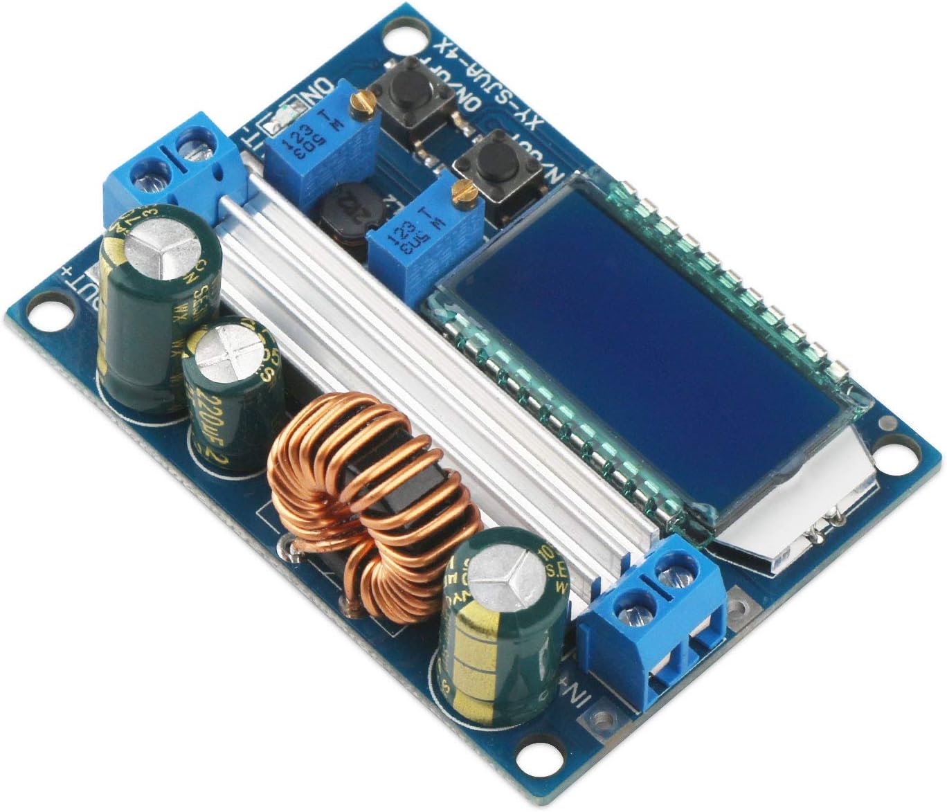


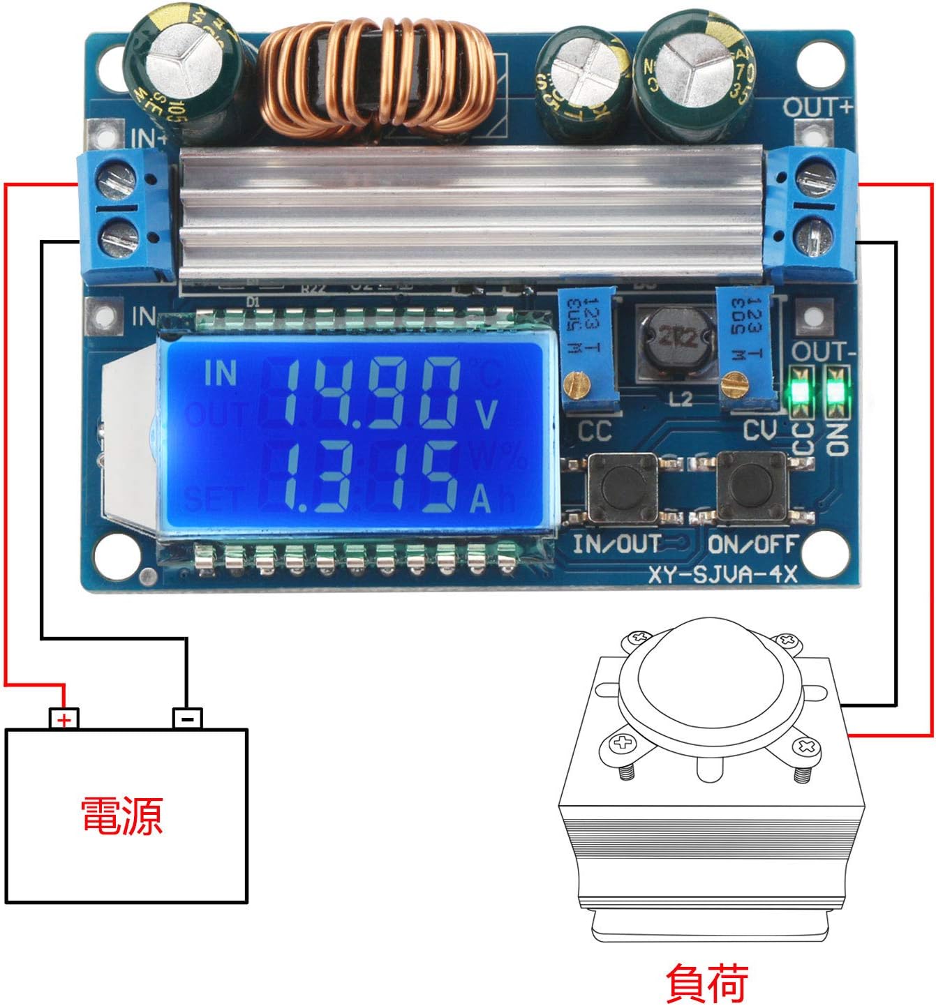
5. Setup and Connections
Before connecting the module, ensure your power source and load are within the specified voltage and current ranges. Observe proper polarity to prevent damage.
5.1 Terminal Connections
- IN+: Positive input terminal. Connect to the positive (+) pole of your DC power source.
- IN-: Negative input terminal. Connect to the negative (-) pole of your DC power source.
- OUT+: Positive output terminal. Connect to the positive (+) pole of your load.
- OUT-: Negative output terminal. Connect to the negative (-) pole of your load.
5.2 Assembly (if applicable)
The module may come with a clear acrylic case. Carefully peel off the protective film from all acrylic pieces. Assemble the case around the module, ensuring all cutouts align with the ports and buttons. Use the provided screws and standoffs to secure the assembly.
6. Operating Instructions
The module features an LCD display and control buttons for easy operation.
6.1 Display Modes and Button Functions
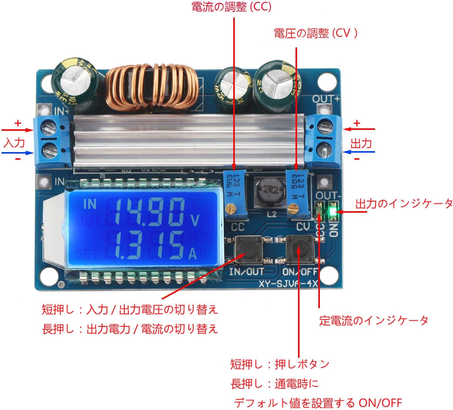
- IN/OUT Button (Short Press): Toggles between displaying input voltage and output voltage.
- IN/OUT Button (Long Press): Toggles between displaying output power (W) and output current (A).
- ON/OFF Button (Short Press): Toggles the output ON or OFF.
- ON/OFF Button (Long Press): Enters/exits the default power-up state setting. When in this mode, a short press of the ON/OFF button will switch the default state between ON and OFF. The selected state will be saved.

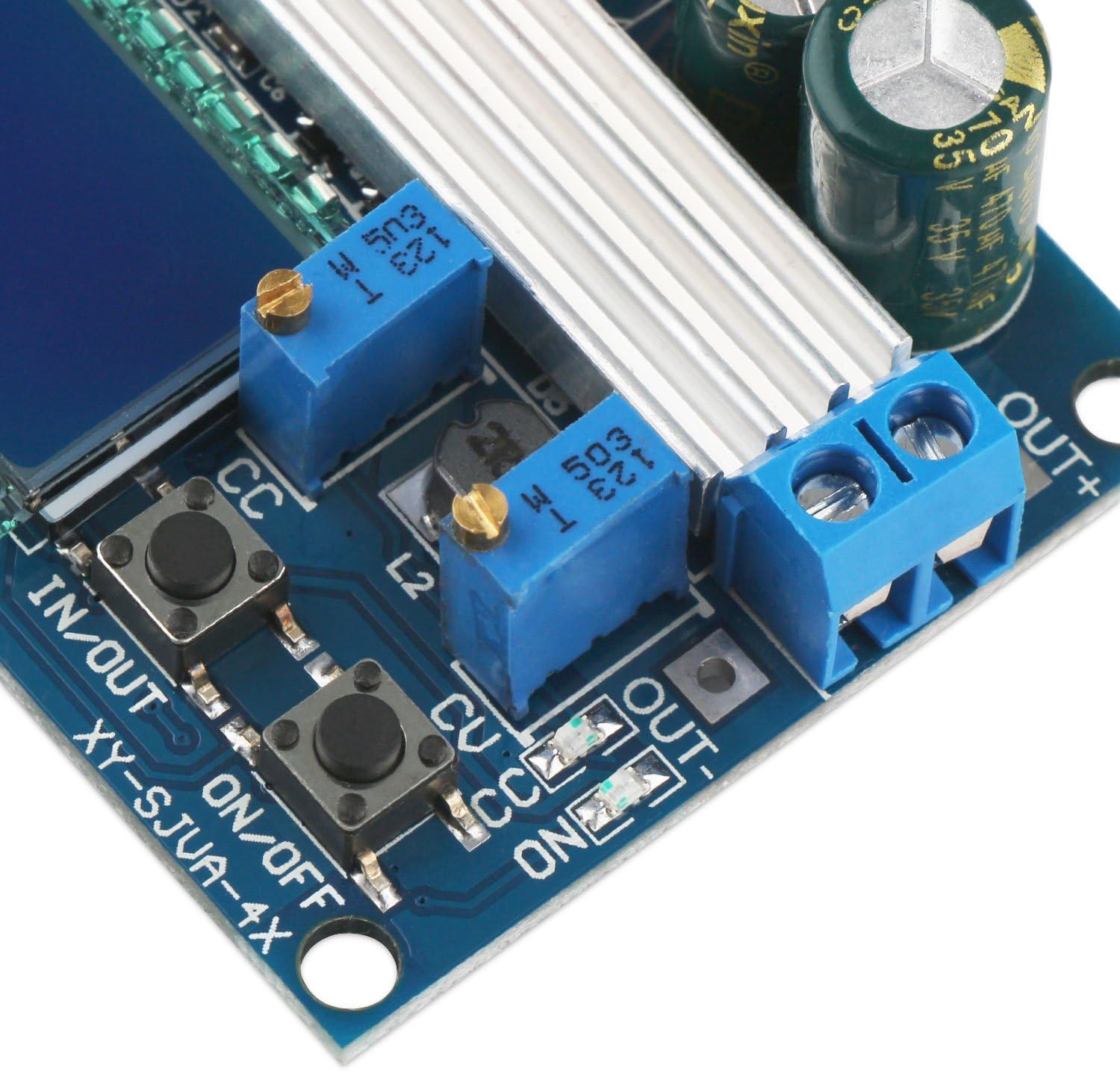
6.2 Voltage and Current Adjustment
The module has two potentiometers for fine-tuning the output voltage and current:
- CV (Constant Voltage) Potentiometer: Adjusts the output voltage. Turn clockwise to increase voltage, counter-clockwise to decrease.
- CC (Constant Current) Potentiometer: Adjusts the constant current limit. Turn clockwise to increase the current limit, counter-clockwise to decrease. This is used for applications like battery charging or driving LEDs.
Note: Use a small screwdriver to adjust these potentiometers. Make adjustments carefully and monitor the output on the LCD or with an external multimeter.
7. Troubleshooting
- No Display/No Output:
- Check input power supply. Ensure it is within the 5.5-30V range.
- Verify input polarity. Reverse connection protection is present, but incorrect wiring should be avoided.
- Ensure the output is not turned OFF via the ON/OFF button.
- Inaccurate Readings:
- If the input voltage is close to 5V (e.g., 5V from a USB power bank), the internal measurements may be inaccurate. Use an external multimeter for precise readings in such cases.
- Output Voltage/Current Not Adjusting:
- Ensure the potentiometers are being turned correctly. They may require multiple turns to see significant changes.
- Check if the module is in constant current (CC) mode if you are trying to adjust voltage but the load is drawing maximum current. The voltage will drop to maintain the set current.
- Module Overheating:
- Ensure adequate ventilation.
- If operating near maximum power (35W-50W) or current (3A-4A), consider adding external heat sinks or forced air cooling.
- Malfunction on Startup with High Load:
- The soft start feature is designed to mitigate this, but very high inductive or capacitive loads might still cause issues. Try connecting the load after the module has stabilized.
8. Maintenance
The DROK Buck-Boost Converter module requires minimal maintenance. Keep the module clean and free from dust and debris. Avoid exposing it to moisture or extreme temperatures. Periodically check connections for tightness and ensure no wires are frayed or damaged.
9. Safety Information
- Always ensure correct input and output polarity before powering on the module.
- Do not exceed the maximum specified input voltage, output current, or output power.
- This module generates heat during operation. Ensure adequate ventilation, especially when operating at higher power levels.
- Avoid touching the components while the module is powered on, as some parts may become hot.
- Keep out of reach of children.
- If you are unsure about any aspect of connecting or operating this module, consult a qualified professional.


