1. Introduction
This manual provides essential information for the installation, operation, and maintenance of your Topteng Speed Sensor. Please read this manual thoroughly before installation to ensure proper function and longevity of the product.
The Topteng Speed Sensor is a high-quality aftermarket component designed to provide accurate speed readings for compatible Harley-Davidson motorcycles. It is engineered for stable performance and high reliability.
2. Product Compatibility
This speed sensor is specifically designed for the following Harley-Davidson models:
- Harley XL Sportster 883 (2004-2005 & 2010-2012)
- Harley XL Sportster 1200 (2004-2005 & 2010-2012)
Important: Please confirm the exact year and model of your motorcycle before ordering and installation to ensure proper fitment.
3. Product Overview
The Topteng Speed Sensor is a critical component for your motorcycle's speedometer and overall engine management system. It accurately measures the rotational speed of a specific part of the transmission, converting it into an electrical signal that the motorcycle's electronic control unit (ECU) interprets as vehicle speed.
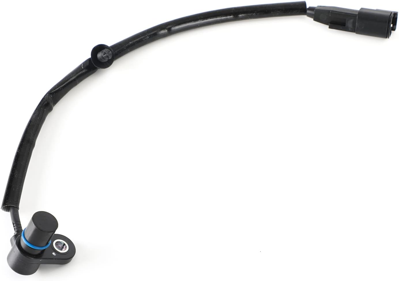
Figure 3.1: Overall view of the Topteng Speed Sensor, showing the sensor head, cable, and connector.

Figure 3.2: Close-up view of the sensor head, featuring the magnetic pickup and mounting point.

Figure 3.3: Detailed view of the electrical connector, ensuring a secure and reliable connection to the motorcycle's wiring harness.
4. Installation (Setup)
Installation of the speed sensor typically involves replacing the existing sensor. It is recommended that this procedure be performed by a qualified motorcycle technician. Always refer to your motorcycle's specific service manual for detailed, model-specific instructions.
General Installation Steps:
- Safety First: Ensure the motorcycle is turned off, the ignition is in the 'OFF' position, and the battery is disconnected to prevent accidental electrical shorts.
- Locate the Old Sensor: Identify the existing speed sensor on your motorcycle. It is typically located near the transmission or primary drive.
- Disconnect Wiring: Carefully disconnect the electrical connector from the old sensor.
- Remove Old Sensor: Unscrew or unbolt the old sensor from its mounting point. Be mindful of any O-rings or gaskets.
- Prepare New Sensor: Ensure the new Topteng sensor is clean and free of debris. If applicable, apply a thin layer of clean engine oil to the new O-ring (if supplied) to aid in installation and sealing.
- Install New Sensor: Carefully insert the new sensor into the mounting hole. Hand-tighten first, then use a wrench to tighten to the manufacturer's specified torque. Do not overtighten.
- Connect Wiring: Reconnect the electrical connector to the new sensor, ensuring a firm and secure connection.
- Reconnect Battery: Reconnect the motorcycle's battery.
- Test Functionality: Start the motorcycle and perform a low-speed test ride to verify that the speedometer is functioning correctly and there are no warning lights related to the speed sensor.
Note: Some models may require clearing fault codes after sensor replacement. Consult your motorcycle's service manual for details.
5. Operating Principles
The Topteng Speed Sensor operates on the principle of electromagnetic induction. As a rotating component (e.g., a gear or reluctor wheel within the transmission) passes by the sensor's tip, it creates changes in a magnetic field. The sensor converts these magnetic field changes into electrical pulses. The frequency of these pulses is directly proportional to the speed of the rotating component, and thus, the vehicle's speed.
These electrical pulses are sent to the motorcycle's ECU, which then processes this data to display the speed on the speedometer and to inform other systems that rely on speed input, such as fuel injection, ignition timing, and cruise control.
6. Maintenance
The Topteng Speed Sensor is designed for durability and requires minimal maintenance. However, periodic inspection can help ensure its continued reliable operation:
- Visual Inspection: Periodically check the sensor and its wiring for any signs of physical damage, corrosion, or fraying. Ensure the connector is securely seated.
- Cleanliness: Keep the area around the sensor free from excessive dirt, grime, or metallic debris, which could interfere with its magnetic readings. Use a soft cloth to gently wipe the sensor tip if accessible.
- Cable Routing: Verify that the sensor cable is properly routed and secured, preventing it from rubbing against moving parts or hot engine components.
Do not attempt to disassemble the sensor, as it is a sealed unit and doing so will void any potential warranty.
7. Troubleshooting
If you experience issues with your speedometer or related systems after installing the Topteng Speed Sensor, consider the following troubleshooting steps:
| Symptom | Possible Cause | Solution |
|---|---|---|
| Speedometer not working or erratic | Loose or corroded electrical connection Damaged wiring Incorrect sensor installation Faulty sensor (less likely if new) | Check and secure all connections. Clean any corrosion. Inspect wiring for cuts or pinches. Repair or replace as needed. Re-check installation steps, ensure sensor is fully seated. If all else fails, test sensor with a multimeter (refer to service manual for specs) or consult a professional. |
| Check Engine Light (CEL) related to speed sensor | Sensor signal issue ECU fault code not cleared | Verify sensor connection and functionality. Use a diagnostic tool to read and clear fault codes. If the code returns, further diagnosis is needed. |
| Inaccurate speed reading | Incorrect tire size (if applicable) Sensor not fully seated Internal sensor issue | Ensure tire size matches motorcycle specifications or recalibrate speedometer if possible. Re-check sensor installation. Consult a professional for diagnosis. |
For complex issues, it is always recommended to consult a certified motorcycle mechanic or refer to your motorcycle's official service manual.
8. Specifications
| Attribute | Value |
|---|---|
| Brand | Topteng |
| Manufacturer Part Number | M582-A024~PMS003AMUS |
| Item Model Number | 3280404B 32804-04B 32804-04A 1022-0199 |
| Specific Uses For Product | Motorcycle |
| Mounting Type | Wheel Mount (refers to sensor's function, not physical mounting) |
| Country of Origin | China |
| First Available Date | January 14, 2022 |
9. Warranty Information
Topteng products are manufactured to high standards. For specific warranty terms and conditions, please refer to the product packaging or contact Topteng customer support directly. Keep your proof of purchase for any warranty claims.
10. Customer Support
For further assistance, technical support, or inquiries regarding your Topteng Speed Sensor, please contact Topteng customer service through their official channels. You can often find contact information on the product packaging or by visiting the official Topteng store page on Amazon:


