Introduction
This manual provides detailed instructions for the installation, operation, and maintenance of your darkFlash DLC29 All Mesh PC Case. Designed as an ATX Mid Tower, this case prioritizes high cooling performance and broad compatibility for various PC components. Please read this manual thoroughly before beginning assembly to ensure proper setup and optimal performance.

Image: The darkFlash DLC29 PC case with its mesh panels detached, illustrating the internal chassis and the full mesh design of the side and top panels.
Key Features
- Stylish Modern Design: Features fine mesh panels on all sides for efficient airflow and dust filtration. Includes an integrated GPU supporter.
- Motherboard Support: Compatible with ATX, M-ATX, and ITX motherboard form factors.
- Component Compatibility: Supports Graphics Processing Units (GPUs) up to 330mm in length and CPU coolers up to 165mm in height. Designed for bottom-mounted ATX power supplies.
- Powerful Cooling System: Accommodates up to 6 fans simultaneously. Supports liquid coolers in sizes 120mm, 140mm, 240mm, 280mm, and 360mm for enhanced thermal management.
- Multifunctional I/O Panel: Conveniently located on the top, featuring 2x USB 3.0 ports, 2x USB 2.0 ports, HD Audio jacks, and Power/Reset buttons.
- Sufficient Internal Space: Case dimensions are 385mm (L) x 210mm (W) x 478mm (H). Offers flexible storage options with 4 or 5 (2.5-inch) drive bays and 2 or 1 (3.5-inch) drive bays. Provides 9 expansion slots.

Image: An illustration demonstrating the airflow pattern within the DLC29 case, with blue arrows indicating cool air intake from the front and sides, and orange arrows showing warm air exhaust from the top.
Specifications
| Brand | darkFlash |
| Model Name | DLC29 |
| Item Model Number | HU-XI-58 |
| Case Type | Mid Tower |
| Material | Metal |
| Color | Black |
| Product Dimensions (LxWxH) | 11.02 x 18.11 x 22.05 inches (385 x 210 x 478 mm) |
| Item Weight | 14.97 pounds |
| Motherboard Compatibility | ATX, M-ATX, ITX |
| Max GPU Length | 330mm |
| Max CPU Cooler Height | 165mm |
| Power Supply Mounting Type | Bottom Mount (ATX) |
| Cooling Method | Air, Water |
| Fan Support | Up to 6 fans (120mm/140mm) |
| Radiator Support | 120mm, 140mm, 240mm, 280mm, 360mm |
| Drive Bays (2.5" SSD) | 4 or 5 |
| Drive Bays (3.5" HDD) | 2 or 1 |
| Expansion Slots | 9 |
| Front I/O Ports | 2x USB 3.0, 2x USB 2.0, HD Audio, Power, Reset |

Image: Technical drawing displaying the external dimensions of the darkFlash DLC29 case, including its width (210mm), depth (385mm), and height (478mm).
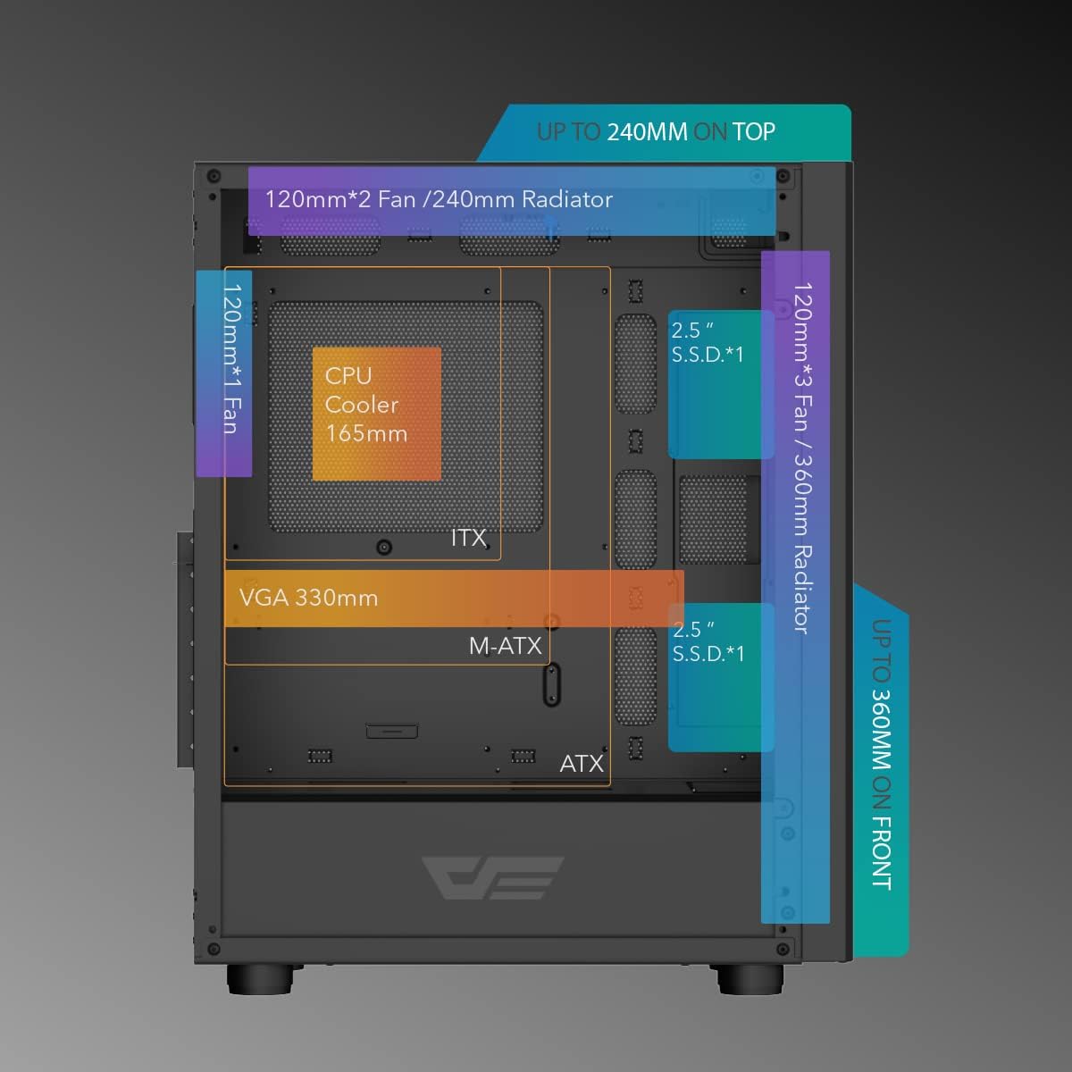
Image: An internal diagram of the DLC29 case, highlighting compatible component sizes such as CPU cooler height (165mm), VGA length (330mm), and various fan/radiator configurations for the front, top, and rear.

Image: A view of the rear interior of the DLC29 case, detailing the mounting locations for 2.5-inch SSDs, 3.5-inch HDDs, and the dedicated compartment for the ATX power supply.
Setup and Installation
This section outlines the general steps for assembling your PC components within the darkFlash DLC29 case. For specific component installation, refer to your component's individual manuals.
- Unpacking: Carefully remove the PC case from its packaging. Inspect for any damage during transit.
- Panel Removal: Remove the side panels to access the interior. The mesh panels are typically secured with thumbscrews or a clip mechanism.
- Motherboard Installation: Install the standoffs (if not pre-installed) according to your motherboard's form factor (ATX, M-ATX, ITX). Secure the motherboard into place.
- CPU and CPU Cooler Installation: Install your CPU and then the CPU cooler (air or liquid) onto the motherboard before or after installing the motherboard into the case, depending on the cooler's size and case access. Ensure the CPU cooler height does not exceed 165mm.
- Graphics Card (GPU) Installation: Insert your GPU into the appropriate PCIe slot. Ensure the GPU length does not exceed 330mm. Utilize the included GPU supporter for stability if needed.
- Power Supply Unit (PSU) Installation: Mount the ATX power supply in the bottom compartment of the case.
- Storage Device Installation: Install 2.5-inch SSDs and 3.5-inch HDDs into their designated bays. The case offers flexible configurations for these drives.
- Fan and Radiator Installation: Install additional cooling fans (up to 6) or liquid cooling radiators (120mm/140mm/240mm/280mm/360mm) in the designated front, top, and rear mounting points.
- Cable Management: Route all power and data cables through the provided cutouts and tie-down points behind the motherboard tray to ensure clean aesthetics and unobstructed airflow.
- Final Assembly: Reattach the side panels. Connect all external peripherals.

Image: An exploded diagram of the DLC29 case, illustrating how the front, top, and side mesh panels can be detached from the main chassis for easier component installation and maintenance.
Operating Instructions
Operating the darkFlash DLC29 PC case involves basic interaction with its front I/O panel.
- Power On/Off: Press the power button located on the top I/O panel to turn your system on or off. A short press typically powers on, while a longer press may initiate a forced shutdown.
- Reset Button: Use the reset button for a quick system restart if necessary.
- USB Ports: Utilize the 2x USB 3.0 and 2x USB 2.0 ports for connecting peripherals such as keyboards, mice, external drives, and other USB-compatible devices.
- HD Audio Jacks: Connect your headphones or microphone to the dedicated HD Audio jacks for audio input and output.
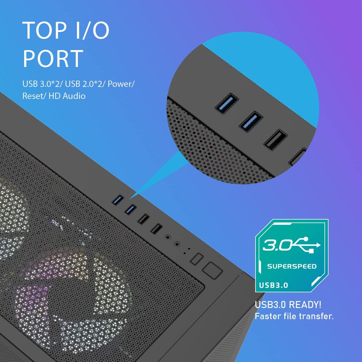
Image: A detailed view of the top I/O panel of the DLC29 case, showing the arrangement of the USB 3.0, USB 2.0, HD Audio ports, and power/reset buttons.
Maintenance
Regular maintenance helps ensure the longevity and optimal performance of your darkFlash DLC29 PC case and the components within.
- Dust Filter Cleaning: The mesh panels act as dust filters. Periodically remove the panels and gently clean them using compressed air or a soft brush to remove accumulated dust. This maintains optimal airflow.
- Interior Cleaning: With the system powered off and unplugged, use compressed air to clear dust from internal components such as CPU coolers, GPU fans, and power supply vents.
- Cable Management Check: Occasionally inspect cable routing to ensure no cables have come loose or are obstructing airflow.
- Exterior Cleaning: Wipe the exterior surfaces with a soft, damp cloth. Avoid abrasive cleaners or solvents.
Troubleshooting
This section addresses common issues you might encounter with your PC case. For complex system issues, consult a qualified technician or your component manufacturers' support.
- System Not Powering On:
- Ensure the power supply is properly connected to the wall outlet and the PSU switch is in the 'ON' position.
- Verify all internal power cables (24-pin motherboard, CPU, GPU) are securely seated.
- Check that the front panel power switch cable is correctly connected to the motherboard's F_PANEL header.
- Overheating Issues:
- Confirm all case fans are spinning and oriented correctly for optimal airflow (intake at front/bottom, exhaust at rear/top).
- Clean dust filters and internal components as described in the Maintenance section.
- Ensure CPU cooler and GPU heatsinks are free of dust and fans are functioning.
- Front I/O Ports Not Working:
- Check that the USB and HD Audio cables from the front panel are correctly connected to the corresponding headers on your motherboard.
- Ensure motherboard drivers are installed and up to date.
- Excessive Noise:
- Identify the source of the noise (fans, hard drives).
- Ensure all fans are securely mounted and free from cable obstruction.
- If using traditional hard drives, ensure they are properly secured in their bays to minimize vibration.
Warranty and Support
For warranty information, technical support, or service inquiries regarding your darkFlash DLC29 PC Case, please refer to the official darkFlash website or contact their customer support directly. Keep your proof of purchase for warranty claims.
Official darkFlash Website: darkFlash Store on Amazon