1. Introduction
The Wishiot TF-Luna is a compact, single-point LiDAR (Light Detection and Ranging) module designed for precise distance measurement. Utilizing the Time-of-Flight (TOF) principle, it offers an operating range of 0.2 meters to 8 meters. This sensor is built with advanced algorithms to ensure reliable performance across various application environments and supports multiple adjustable configurations. Its small size and low power consumption make it suitable for integration into a wide range of projects, including robotics, drone altitude holding, obstacle detection, and smart devices.
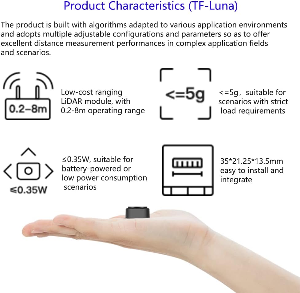
Image: The TF-Luna LiDAR sensor, illustrating its compact form factor and key characteristics such as 0.2-8m operating range and less than 0.35W power consumption, making it suitable for battery-powered applications.
2. Specifications
Below are the detailed technical specifications for the TF-Luna LiDAR Range Finder Sensor:
| Parameter | Value |
|---|---|
| Model | TF-Luna |
| Operating Range | 0.2m ~ 8m |
| Distance Resolution | 1 cm |
| Supply Voltage | 5V ± 0.1V |
| Average Current | ≤ 70mA |
| Peak Current | 150mA |
| Average Power | 350mW |
| Communication Interface | UART/I2C (Default UART) |
| Frame Rate | 1 ~ 250Hz (adjustable) |
| Communication Level | TTL Level (3.3V) |
| Default Baud Rate | 115200 |
| Data Bit | 8 |
| Stop Bit | 1 |
| Parity Check | None |
| Light Source | VCSEL |
| Wavelength | 850nm |
| Operating Temperature | -20°C ~ 75°C |
| Field of View (FoV) | 2 degrees |
| Net Weight | < 5g |
| Dimensions | 35 x 21.25 x 13.5 mm |
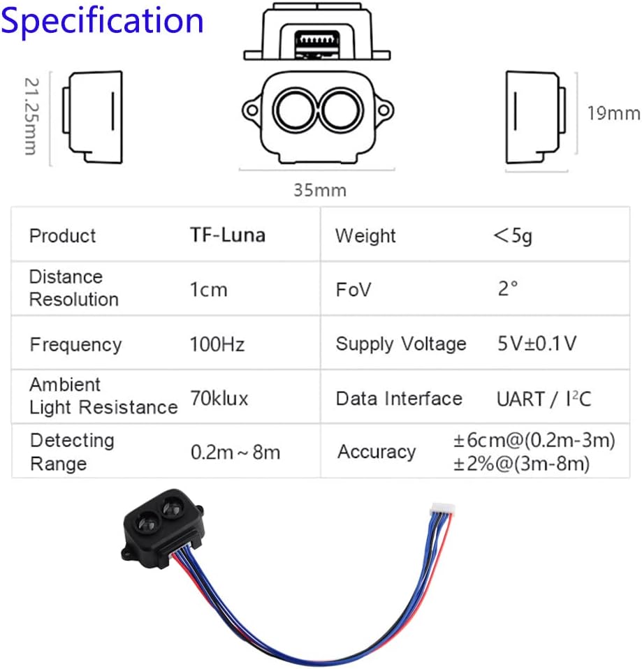
Image: A visual representation of the TF-Luna LiDAR sensor's dimensions and a table summarizing its key specifications including operating range, resolution, power, and communication interfaces.
3. Package Contents
The TF-Luna LiDAR Range Finder Sensor package typically includes the following items:
- 1 x TF-Luna LiDAR Range Finder Sensor Module
- 1 x 1.25mm-6Pin Male to Male connector wire
- 1 x 1.25mm-6Pin Male Connector to Male Dupont Cable
- 1 x 1.25mm-6Pin Male Terminal to Female Dupont Wire
Note: The specific types and quantities of cables may vary slightly. Always verify the contents upon receipt.
4. Setup and Wiring
Proper wiring is crucial for the correct operation of the TF-Luna sensor. The module supports both UART and I2C communication interfaces. By default, it operates in UART mode. I2C communication can be enabled by specific wiring configurations.
4.1. General Wiring Guidelines
- Power Supply: The TF-Luna requires a 5V power supply. Connect the +5V pin on the sensor to your 5V power source and the GND pin to your system's ground.
- Polarity Warning: This product does not have polarity or over-voltage protection. Incorrect wiring can damage the sensor. Always double-check your connections before applying power. Pay close attention to wire colors and pin assignments, as some included cables may have non-standard color coding (e.g., red for ground, black for VCC). Refer to the pinout diagram below.
- Communication Interface:
- UART (Default): Connect the RXD/SDA pin of the TF-Luna to the TX pin of your microcontroller, and the TXD/SCL pin of the TF-Luna to the RX pin of your microcontroller.
- I2C: To use I2C, specific wiring or configuration might be required. Consult the official TF-Luna documentation for detailed I2C setup instructions if the default UART is not desired.
4.2. Wiring Diagram Example (WiFi LoRa 32)
This example illustrates connecting the TF-Luna to a WiFi LoRa 32 board. Ensure your IDE has the necessary Heltec ESP32 Series Dev-boards installed for WiFi_LoRa_32 compatibility.

Image: A detailed wiring diagram showing the connection of the TF-Luna LiDAR sensor to a WiFi LoRa 32 (V2) board, including pin assignments for 5V, RX/SDA, TX/SCL, and GND. Note the explicit warning that WiFi LoRa 32 is not included.
- TF-Luna 5V to WiFi LoRa 32 5V
- TF-Luna LiDAR RX to WiFi LoRa 32 PIN 23 TXD
- TF-Luna LiDAR TX to WiFi LoRa 32 PIN 22 RXD
- TF-Luna GND to WiFi LoRa 32 GND
4.3. Schematic Diagram for TF-Luna with Raspberry Pi Pico
This diagram shows how to connect the TF-Luna to a Raspberry Pi Pico. The Pico is not included with the sensor.

Image: A schematic diagram illustrating the connection between the TF-Luna LiDAR sensor and a Raspberry Pi Pico, detailing the SDA, SCL, 5V power supply, and GND connections. The diagram clarifies that the Raspberry Pi Pico is not included.
- TF-Luna SDA (White line) to RPi Pico SDA
- TF-Luna SCL (Green line) to RPi Pico SCL
- TF-Luna 5V Power Supply (Red line) to RPi Pico 5V
- TF-Luna GND (Black line) to RPi Pico GND
5. Operating Principles
The TF-Luna operates on the Time-of-Flight (TOF) principle. It emits a modulated light pulse and measures the time it takes for the light to travel to an object and return to the sensor. This time difference is then used to calculate the distance to the object. The sensor's internal algorithms process this data to provide accurate and stable distance readings. The frame rate is adjustable from 1 to 250Hz, allowing users to optimize data acquisition speed for their specific application needs.
6. Applications
The TF-Luna LiDAR sensor is versatile and suitable for a variety of applications due to its compact size, accuracy, and adjustable parameters. Major application areas include:
- Traffic Monitoring: For vehicle detection and traffic flow analysis.
- Obstacle Detection and Avoidance: In robotics, drones, and autonomous vehicles.
- Level Measurement: For liquids or granular materials in industrial settings.
- Smart Devices: Integration into smart home systems or interactive displays.
- Security Systems: Intrusion detection and area monitoring.
- Drone Altitude Holding and Terrain Following: Enhancing drone stability and navigation.
- Machine Control and Safety Sensors: For industrial automation and safety protocols.
- Distance Measuring Instruments: General purpose distance measurement.
- Auxiliary Focus: For camera systems.
- Elevator Projection: For detecting presence.
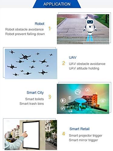
Image: An infographic showcasing diverse applications of the TF-Luna LiDAR sensor, such as robot obstacle avoidance, UAV altitude holding, smart city solutions (e.g., smart toilets, trash bins), and smart retail triggers (e.g., projector, mirror).
7. Maintenance
The TF-Luna LiDAR sensor is designed for durability, but proper care ensures its longevity and performance:
- Keep Clean: Ensure the optical lens is free from dust, dirt, and moisture. Use a soft, lint-free cloth for cleaning if necessary. Avoid abrasive materials or harsh chemicals.
- Environmental Conditions: Operate the sensor within its specified temperature range (-20°C to 75°C). Avoid exposure to extreme humidity, direct sunlight for prolonged periods, or corrosive environments.
- Physical Protection: While robust, avoid dropping the sensor or subjecting it to strong impacts. Ensure it is securely mounted in its intended application.
- Power Supply: Always use a stable 5V power supply within the specified tolerance. Over-voltage can permanently damage the module.
8. Troubleshooting
If you encounter issues with your TF-Luna sensor, consider the following troubleshooting steps:
- No Power/No Response:
- Verify the 5V power supply is correctly connected and stable.
- Crucial: Double-check all wiring connections, especially power (VCC) and ground (GND). Be aware that some included cables may have non-standard color coding (e.g., red for ground, black for VCC). Incorrect polarity will damage the sensor.
- Ensure the connector is fully seated and not loose.
- Communication Errors (UART):
- Confirm the baud rate (default 115200) matches your microcontroller's settings.
- Check RX/TX connections are correctly crossed (sensor TX to microcontroller RX, sensor RX to microcontroller TX).
- Verify communication levels (TTL Level 3.3V).
- Inaccurate or Unstable Readings:
- Ensure the sensor's optical window is clean and unobstructed.
- Check for strong ambient light sources directly impacting the sensor, which can affect performance.
- Verify the target object is within the specified operating range (0.2m to 8m) and has sufficient reflectivity.
- Consider environmental factors like fog, smoke, or heavy dust, which can interfere with LiDAR operation.
- I2C Not Working:
- Ensure the sensor is correctly configured for I2C mode (if applicable, via wiring or software command).
- Verify SDA and SCL connections.
- Check for proper pull-up resistors on the I2C lines if not provided by your microcontroller.
For further technical assistance, refer to the official documentation provided by the manufacturer or contact their support channels.
9. Warranty and Support
Warranty: The Wishiot TF-Luna LiDAR Range Finder Sensor comes with a warranty period of one month from the date of purchase. This warranty covers manufacturing defects under normal use conditions. Please retain your proof of purchase for warranty claims.
Support: For technical inquiries, troubleshooting assistance beyond this manual, or warranty claims, please contact the seller or manufacturer directly. You can typically find contact information on the product's purchase page or the manufacturer's official website.
Note: Damage resulting from improper installation, incorrect wiring (especially regarding polarity), unauthorized modifications, or operation outside specified environmental conditions may void the warranty.


