1. Introduction
This manual provides detailed instructions for the installation, operation, and maintenance of your DieseRC AC 240V 230V 220V Wireless Relay Remote Control Switch. Please read this manual thoroughly before use to ensure proper function and safety.

Figure 1: DieseRC Wireless Relay Remote Control Switch Kit
The kit includes a receiver board and two remote control transmitters, designed for various applications such as garage doors, lamps, electric curtains, and motors.
2. Safety Information
- Always disconnect power before installing or servicing the device.
- Ensure all wiring is performed by a qualified electrician and complies with local electrical codes.
- Do not expose the device to moisture or extreme temperatures.
- Verify the voltage and current ratings of your connected devices do not exceed the relay's specifications (10A, 85V-240V AC).
- Keep remote controls out of reach of children.
3. Product Overview
The DieseRC Wireless Relay Remote Control Switch is a 2-channel 433Mhz RF relay receiver designed for remote control applications. It offers stable and reliable performance with high reception sensitivity.
3.1 Key Features
- Wireless RF 433 MHz: Stable and reliable performance with high sensitivity.
- Long Range: Control devices up to 50 meters without obstacles.
- Multiple Operating Modes: Momentary, Toggle, and Latched modes.
- Independent Relays: Two independent relays for controlling separate devices.
- Wide Voltage Compatibility: Receiver suitable for 85V ~ 240V AC.
- High Quality Relays: Rated for over 100,000 uses.
3.2 Components
- Receiver Board: The main unit that receives signals and controls connected devices.
- Remote Transmitters: Handheld devices for sending control signals.

Figure 2: Receiver Board Details
This image highlights the Normally Open (NO), Common (COM), Normally Closed (NC) pins, the antenna, indicator light, and the learning button on the receiver board.
4. Specifications
| Feature | Specification |
|---|---|
| Model Number | 2202 |
| Working Voltage | AC 85V-250V |
| Output Voltage | 1V-250V |
| Max Current | 10A |
| RF Frequency | 433Mhz |
| Remote Control Distance | Up to 50 meters (open area) |
| Operating Modes | Momentary, Toggle, Latched |
| Contact Material | Silver Alloy |
| Dimensions (L x W x H) | 7.5 x 5.5 x 3 cm |
| Weight | 140 grams |
5. Setup and Wiring
Carefully follow these instructions for proper installation and pairing.
5.1 Wiring Diagrams
The receiver board features Normally Open (NO), Common (COM), and Normally Closed (NC) terminals for each of its two independent relays. Ensure correct wiring based on your application.
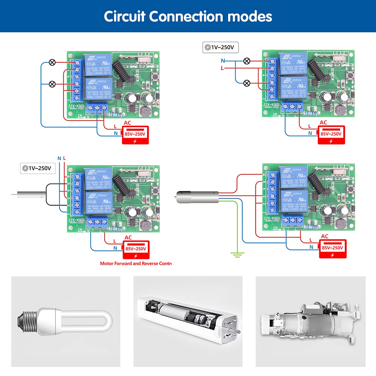
Figure 3: Circuit Connection Modes
This diagram illustrates different wiring configurations for connecting lights and motors (AC and DC) to the relay receiver.
5.2 Pairing Remote Transmitters (Learning Modes)
The receiver supports three operating modes: Momentary, Toggle, and Latched. Each mode requires a specific number of presses on the learning button to pair the remote.

Figure 4: Remote Pairing Instructions
This image details the steps to set up the remote control for Momentary, Toggle, and Latched modes by pressing the learning button 1, 2, or 3 times respectively, then pressing the A and B buttons on the remote.
- Momentary Mode (Press 1 time): Press the learning button on the receiver once. Then, press button 'A' on the remote. Wait approximately 3 seconds. Press button 'B' on the remote. The pairing is successful. In this mode, the relay activates only while the remote button is pressed.
- Toggle Mode (Press 2 times): Press the learning button on the receiver twice. Then, press button 'A' on the remote. Wait approximately 3 seconds. Press button 'B' on the remote. The pairing is successful. In this mode, one press turns the device ON, another press turns it OFF.
- Latched Mode (Press 3 times): Press the learning button on the receiver three times. Then, press button 'A' on the remote. Wait approximately 3 seconds. Press button 'B' on the remote. The pairing is successful. In this mode, pressing 'A' turns Relay 1 ON and turns Relay 2 OFF. Pressing 'B' turns Relay 2 ON and turns Relay 1 OFF. Note: This mode requires a remote control with at least 3 buttons for full functionality.
5.3 Resetting the Receiver
To clear all paired remote controls from the receiver's memory:

Figure 5: Reset Procedure
Press the learning button 8 times to reset the receiver and clear all stored remote control pairings.
- Press the learning button on the receiver 8 times.
- The indicator light will flash, confirming that all remote controls have been cleared.
6. Operating the Device
Once the remote control is paired, you can operate your connected devices according to the selected mode.
6.1 Momentary Mode Operation
In Momentary Mode, the relay activates only while the remote button is held down. Releasing the button deactivates the relay.

Figure 6: Momentary Mode
Press and hold the remote button to turn on the connected device. Release the button to turn it off.
6.2 Toggle Mode Operation
In Toggle Mode, a single press of the remote button switches the relay state (ON to OFF, or OFF to ON).

Figure 7: Toggle Mode
Press the remote button once to turn on the connected device. Press the same button again to turn it off.
6.3 Latched Mode Operation
In Latched Mode, one button turns a relay ON, and another button turns it OFF (and simultaneously turns the other relay ON if applicable).

Figure 8: Latched Mode
Press button 'A' to turn Relay 1 ON. Press button 'B' to turn Relay 2 ON, and at the same time, Relay 1 will turn OFF.
6.4 Example Applications
The wireless relay switch can be used for various applications, including:
- Garage door control
- Electric gate control
- Lighting control
- Electric curtain control
- Motor control (AC and DC)

Figure 9: Garage Door Control Example
This illustration demonstrates how the relay receiver can be wired to remotely control a garage door motor.
Video 1: Programming and Operation Modes Demonstration
This video demonstrates the process of programming the remote control for Momentary, Toggle, and Latched modes, and shows the operation of lights and motors using the paired remote.
7. Maintenance
The DieseRC Wireless Relay Remote Control Switch requires minimal maintenance. Follow these guidelines to ensure longevity:
- Keep the receiver and remote controls clean and dry.
- Avoid dropping or subjecting the devices to strong impacts.
- Replace remote control batteries as needed (1 x 12V battery included).
- Periodically check wiring connections for security and integrity.
8. Troubleshooting
If you encounter issues with your device, refer to the following common problems and solutions:
- Device not responding to remote:
- Check if the remote control battery is dead and replace it.
- Ensure the receiver is powered on.
- Re-pair the remote control to the receiver following the instructions in Section 5.2.
- Ensure the remote is within the effective operating range (up to 50 meters without obstacles).
- Device not turning ON/OFF correctly:
- Verify the wiring connections are correct for your desired application (refer to Section 5.1).
- Confirm the operating mode is correctly set (Momentary, Toggle, or Latched) as per Section 5.2.
- Check if the connected device is functioning properly independently of the relay.
- Short range or intermittent control:
- Ensure there are no significant obstacles (thick walls, metal structures) between the remote and the receiver.
- Check for sources of RF interference in the vicinity.
- Ensure the receiver's antenna is not obstructed or damaged.
9. Warranty and Support
DieseRC products are designed for quality and reliability. For warranty information or technical support, please refer to the product packaging or contact DieseRC customer service through their official channels. Keep your purchase receipt for warranty claims.


