1. Introduction
This manual provides essential information for the proper installation, operation, and maintenance of your BETAFPV ExpressLRS Lite Receiver with Flat SMD Ceramic Antenna V1.2. Please read these instructions carefully before use to ensure optimal performance and longevity of the product.
The BETAFPV ExpressLRS Lite Receiver V1.2 is an advanced 2.4GHz receiver designed for FPV racing drones, offering ultra-low latency, high refresh rates, and extended range performance. It features a compact, lightweight design with an integrated flat SMD ceramic antenna.
Key Features:
- Ultra-thin 3mm board and ultra-lightweight 0.46g design.
- Enlarged soldering pads for simplified installation.
- Optimized impedance matching for enhanced signal reliability and sensitivity.
- Long-range capability: up to 300m at 25mW and 1000m at 50mW transmitter power.
- Low-profile, crash-resistant flat ceramic antenna.

Figure 1: The compact BETAFPV ExpressLRS Lite Receiver V1.2, showcasing its flat ceramic antenna and small form factor.
2. Product Overview
The receiver's design prioritizes both performance and ease of integration into small FPV platforms. The V1.2 iteration includes improvements such as larger soldering pads for easier assembly.

Figure 2: Two BETAFPV ELRS 2.4G Lite Receivers (Flat Antenna V1.2) with text overlays indicating its 0.46g lightweight design, easy soldering with larger pads, 2.4GHz flat SMD ceramic antenna, and up to 1000m range at 50mW/500Hz.

Figure 3: An illustrative diagram showing the difference in soldering pad size between the V1.1 and V1.2 versions, emphasizing the larger, simpler soldering pads on the V1.2 model.
Component Identification:

Figure 4: Top-down view of the receiver, labeling the Wifi Antenna, ESP8285 microcontroller, GND, 5V, TX, and RX pads.

Figure 5: Bottom-up view of the receiver, labeling the 2.4G Flat SMD Antenna, LED indicator, SX1281 RF chip, and Firmware Upgrade Pad.
3. Setup
Wiring Diagram:
Connect the ELRS Lite Receiver to your Flight Controller (FC) as shown in the diagram below. Ensure correct polarity and signal connections.
- FC TX to Receiver RX
- FC RX to Receiver TX
- 5V to 5V
- GND to GND
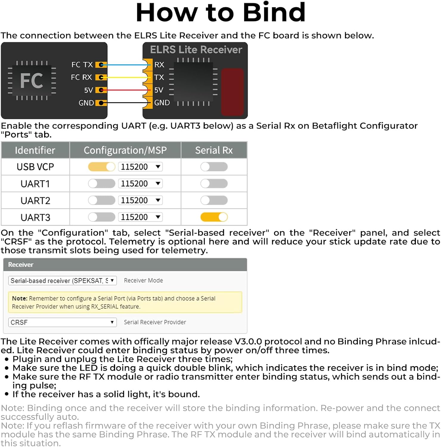
Figure 6: Wiring diagram for connecting the ELRS Lite Receiver to a flight controller, along with Betaflight Configurator settings for enabling Serial Rx.
Binding Procedure:
The Lite Receiver comes with officially released V3.0.0 protocol and does not include a Binding Phrase. To bind the receiver to your transmitter module, follow these steps:
- Plug in and unplug the Lite Receiver three times.
- Observe the LED indicator. It should display a quick double blink, indicating the receiver is in bind mode.
- Ensure your TX module or radio transmitter is in bind mode and sending out a binding pulse.
- If the receiver's LED turns solid, the binding process is complete.
Note: Once bound, the receiver will store the binding information. Re-power the receiver and it should connect automatically. If you reflash the receiver's firmware with your own Binding Phrase, ensure the TX module has the same Binding Phrase for automatic binding.
Firmware Update:
The current firmware version of the Lite Receiver flat antenna V1.2 is ELRS 3.3.0. For flashing official ELRS firmware, download the latest ExpressLRS-Configurator. It is crucial that the TX module and receiver are running the same ELRS version to ensure successful frequency matching and communication.
4. Operating Instructions
Once the receiver is successfully bound and configured in your flight controller, it will provide reliable control for your FPV drone. The optimized impedance matching and flat ceramic antenna contribute to stable signal reception and extended range.
The high refresh rate of ExpressLRS ensures responsive control, critical for precision flying in FPV applications. Monitor your signal strength (RSSI) through your OSD (On-Screen Display) if configured, to maintain awareness of your link quality during flight.
Video 1: This video demonstrates the long-range performance of the ELRS 2.4G Lite Receiver (Flat Antenna V1.2) in an FPV drone, showcasing stable signal reception up to 1000 meters at 50mW transmitter power. The on-screen display indicates increasing flight distance.
5. Maintenance
The BETAFPV ExpressLRS Lite Receiver is designed for durability, but proper care will extend its lifespan:
- Physical Protection: While the flat antenna is crash-resistant, avoid direct impacts. Ensure the receiver is securely mounted within your drone to prevent vibration damage.
- Environmental Conditions: Keep the receiver dry and away from excessive dust or extreme temperatures.
- Cleaning: If necessary, gently clean the receiver with a soft, dry brush. Avoid using liquids or solvents.
- Wiring Integrity: Periodically inspect solder joints and wires for any signs of wear or damage. Replace damaged wires promptly.
6. Troubleshooting
- Binding Issues: Ensure both your TX module and receiver are running the exact same ELRS firmware version. If using a custom binding phrase, verify it matches on both devices. Repeat the binding procedure carefully.
- No Signal/RX Loss: Check all wiring connections between the receiver and flight controller. Verify that the correct UART is enabled for Serial Rx in Betaflight Configurator. Ensure your transmitter is powered on and operating on the correct frequency.
- Reduced Range: Confirm your TX module's power output settings. Ensure the receiver's antenna is not obstructed by carbon fiber or other conductive materials. Check for local RF interference.
- LED Behavior: Refer to the ExpressLRS documentation for specific LED flash codes to diagnose issues. A solid LED typically indicates a successful link.
7. Specifications
| Feature | Specification |
|---|---|
| Model | BETAFPV ExpressLRS Lite Receiver V1.2 |
| Weight | 0.46 g (receiver only), 0.5 g (with flat SMD ceramic antenna) |
| Dimensions | 11 mm x 10 mm x 3 mm |
| Antenna Type | Flat SMD Ceramic Antenna |
| Antenna Gain | 3.2dBi |
| Radio Efficiency | >80% |
| MCU | ESP8285 |
| Telemetry Power | 17mW |
| Frequency Bands | 2.4GHz ISM |
| Input Voltage | 5 V |
| Max Range (25mW TX) | 300m |
| Max Range (50mW TX) | 1000m |
| Number of Channels | 8 |
8. Package Contents
The BETAFPV ExpressLRS Lite Receiver package includes the following items:
- 1 x BETAFPV ELRS Lite Receiver (Flat SMD Ceramic Antenna)
- 2 x Spare Shrink Tubes
- 4 x 30AWG Silicon Connection Wires (1 black, 1 red, 1 white, 1 yellow)

Figure 7: The complete package contents, including the BETAFPV ELRS Lite Receiver, two spare shrink tubes, and four 30AWG silicon connection wires.
9. Support and Warranty
For technical support, firmware updates, or additional product information, please visit the official BETAFPV website or contact their support team directly.
- Website: betafpv.com
- Email Support: support@betafpv.com
Warranty information for this product is provided by BETAFPV. Please refer to the official BETAFPV website or your purchase documentation for details regarding warranty terms and conditions.