1. Introduction
The DORHEA INA219 module is a high-precision, zero-drift, bi-directional DC current and power monitoring sensor with an I2C interface. Designed for energy-saving electronic products, it accurately measures voltage drop across a shunt resistor, senses bus supply voltage, and calculates power. Its compact SOT23 packaging makes it suitable for various applications including servers, notebook computers, power supplies, battery management systems, digital electric vehicles, and telecommunication equipment. The INA219 offers high accuracy with a maximum error of 1% and a maximum offset of 100 µV within a temperature range of -40°C to +85°C. Its 12-bit resolution helps minimize power loss and consumption by reducing the required shunt resistor pressure drop.
2. Product Features
- Single power supply operation: +3.0V to +5.5V.
- Monitors voltage drop across shunt resistor and bus supply voltage.
- Calculates power consumption.
- Zero-drift design for high accuracy.
- Up to 128 samples can be averaged for filtering in noisy environments.
- Maximum error accuracy of 1% and maximum offset of 100 µV.
- 12-bit resolution for precise measurements.
- Sensed bus voltage range: 0V to +26V.
- Software programmable features.
- I2C interface with timeout to prevent bus lock and support high-speed mode (up to 3.4 MHz).
3. Setup and Connection
This section details the physical connections required to integrate the INA219 module into your system.
3.1 Pinout Description
The INA219 module features several pins for power, I2C communication, and current sensing:
- VCC: Power supply for the module (3.0V to 5.5V).
- GND: Ground connection.
- SCL: I2C Clock line.
- SDA: I2C Data line.
- VIN+: Positive input for current sensing (connect to the high side of the shunt resistor).
- VIN-: Negative input for current sensing (connect to the low side of the shunt resistor).
- A0, A1: I2C address selection pins (can be pulled high or low to change the I2C address).
3.2 Typical Wiring Diagram
Connect the INA219 module to your microcontroller (e.g., Arduino, Raspberry Pi) as follows:
- Connect VCC on the INA219 to the 3.3V or 5V output of your microcontroller.
- Connect GND on the INA219 to the Ground of your microcontroller.
- Connect SCL on the INA219 to the SCL pin of your microcontroller.
- Connect SDA on the INA219 to the SDA pin of your microcontroller.
- To measure current, insert a shunt resistor in series with the load. Connect VIN+ to the high side of the shunt (closer to the power source) and VIN- to the low side of the shunt (closer to the load).
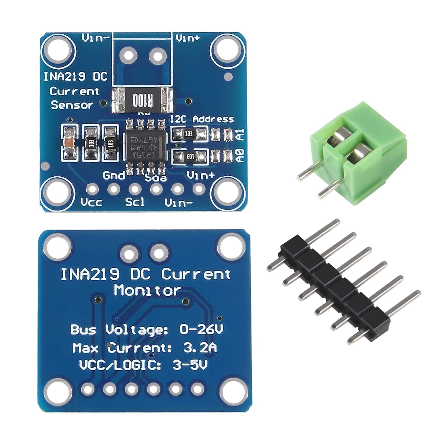
Figure 1: Top view of the INA219 module showing pin labels (VCC, GND, SCL, SDA, VIN+, VIN-, A0, A1) and component layout. The I2C address jumpers A0 and A1 are visible.

Figure 2: Angled view of the INA219 module, illustrating the included header pins for microcontroller connection and the green terminal block for VIN+ and VIN- connections.
4. Operating Instructions
The INA219 communicates via the I2C protocol, allowing a microcontroller to read current, voltage, and power data. Software libraries are available for popular platforms like Arduino and Raspberry Pi to simplify interaction.
4.1 I2C Communication
The module uses a standard I2C interface. Ensure your microcontroller's I2C pins are correctly connected to the INA219's SCL and SDA pins. The default I2C address is typically 0x40, but it can be modified by configuring the A0 and A1 pins. Refer to the INA219 datasheet for specific address configurations.
4.2 Data Acquisition
Once connected and powered, use a compatible software library to initialize the INA219. The library will handle the I2C communication and provide functions to read:
- Bus Voltage: The voltage at the VIN- pin relative to ground.
- Shunt Voltage: The voltage difference between VIN+ and VIN-.
- Current: Calculated from the shunt voltage and the known shunt resistor value.
- Power: Calculated from the bus voltage and current.
The INA219 features programmable calibration registers, allowing direct reading of current in Amperes and power in Watts. It also supports averaging up to 128 samples to improve measurement stability in noisy environments.
5. Maintenance
The INA219 module is a robust electronic component designed for long-term operation with minimal maintenance. Follow these guidelines to ensure optimal performance and longevity:
- Environmental Conditions: Operate the module within its specified temperature range (-40°C to +85°C) and avoid excessive humidity or corrosive environments.
- Cleaning: If necessary, gently clean the module with a soft, dry brush or compressed air to remove dust. Avoid using liquids or abrasive materials.
- Handling: Always handle the module by its edges to prevent damage to components and to minimize electrostatic discharge (ESD).
- Connections: Periodically check all connections to ensure they are secure and free from corrosion.
6. Troubleshooting
If you encounter issues with your INA219 module, consider the following troubleshooting steps:
- No I2C Communication:
- Verify VCC and GND connections are correct and within the 3.0V-5.5V operating range.
- Check SCL and SDA connections to your microcontroller. Ensure pull-up resistors are present on the I2C lines (often built into microcontrollers or breakout boards).
- Confirm the I2C address. Use an I2C scanner sketch/program to detect the module's address. Adjust A0/A1 pins if necessary.
- Incorrect Readings:
- Ensure VIN+ and VIN- are connected correctly across the shunt resistor.
- Verify the shunt resistor value used in your software calibration matches the physical resistor.
- Check for proper grounding of both the INA219 and the circuit being measured.
- Review the INA219 datasheet for correct register configurations (e.g., gain, bus voltage range, averaging).
- Module Not Powering On:
- Double-check VCC and GND connections.
- Measure the voltage at the VCC pin to ensure it is receiving power.
7. Specifications

Figure 3: Bottom view of the INA219 module, showing printed specifications for bus voltage, maximum current, and VCC/Logic voltage.
| Feature | Specification |
|---|---|
| Brand | DORHEA |
| Model Number | INA219 |
| Maximum Supply Voltage (VCC) | 5.5 Volts |
| Operating Voltage (VCC/Logic) | 3.0V to 5.5V (3-5V as printed on module) |
| Bus Voltage Range | 0V to +26V |
| Maximum Current (Module) | 3.2A |
| Measurement Accuracy | ±1% |
| Maximum Offset | 100 µV |
| Output Type | Digital (I2C) |
| I2C Interface Speed | Up to 3.4 MHz (High-speed mode) |
| Resolution | 12-bit |
| Operating Temperature | -40°C to +85°C |
| Item Weight | 1.44 ounces (approx. per 10-pack) |
| Material | Iron (module components) |
8. Warranty Information
DORHEA products are typically covered by a standard manufacturer's warranty against defects in materials and workmanship. For specific warranty terms and conditions, please refer to the product packaging or contact your retailer. Keep your purchase receipt as proof of purchase for any warranty claims.
9. Support
For technical assistance, additional documentation, or inquiries regarding the DORHEA INA219 module, please contact the seller or DORHEA customer support through the platform where the product was purchased. Online resources, community forums, and datasheets for the INA219 chip are also valuable sources of information for advanced users.


