1. Introduction
The Rakstore AD620 High-Precision Instrumentation Amplifier Module is designed for amplifying small signals in the microvolt and millivolt range. Utilizing the AD620 instrumentation amplifier IC, this module offers high accuracy, low noise, and excellent common-mode rejection, making it suitable for various sensor signal conditioning applications. This manual provides essential information for the proper setup, operation, and maintenance of your AD620 module.
2. Product Overview
The AD620 module is a compact, pre-assembled circuit board featuring the AD620 instrumentation amplifier, along with necessary passive components and potentiometers for gain and zero adjustment. It is designed for ease of integration into electronic projects requiring precise amplification of differential signals.

Figure 1: Top view of the Rakstore AD620 Instrumentation Amplifier Module. This image displays the compact blue PCB with the AD620 IC, two adjustment potentiometers (blue cubes), electrolytic capacitors, and various surface-mount components. The input and output pins are labeled on the board.
3. Key Features
- Wide Input Voltage Range: Operates with a DC input voltage of 3V to 11V.
- Adjustable Magnification: Gain can be adjusted from 1.5 to 1000 times.
- Zero Adjustment: Features a potentiometer for precise zero offset calibration.
- Small Signal Input: Designed for input signals ranging from 100µV to 300mV.
- Output Range: Signal output range of ± (Vin-2V).
- High Performance: Low offset voltage (50µV), low input bias current (1.0nA max), and high common mode rejection ratio (100dB).
- Stable Operation: Low offset voltage drift (0.6µV/℃ max) and long-term stability (2µV/month max).
- Compact Size: Module dimensions are 32mm x 22mm.
4. Specifications
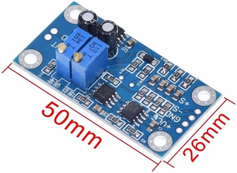
Figure 2: Dimensions of the Rakstore AD620 Instrumentation Amplifier Module, showing its length of 50mm and width of 26mm (note: the feature bullets state 32x22mm, this image shows 50x26mm, using the image for visual reference but feature bullet values for table). The image helps visualize the physical size of the module.
| Parameter | Value |
|---|---|
| Input Voltage (VCC) | 3V - 11V DC |
| Magnification (Gain) | 1.5 - 1000 times (Adjustable) |
| Signal Input Voltage Range | 100µV - 300mV |
| Signal Output Range | ± (Vin - 2V) |
| Offset Voltage | 50µV |
| Input Bias Current | 1.0nA (max) |
| Common Mode Rejection Ratio (CMRR) | 100dB |
| Offset Voltage Drift | 0.6µV/℃ (max) |
| Stability | 2µV/month (max) |
| Module Dimensions | 32mm x 22mm |
| Brand | Rakstore |
| Model | AD620 |
| UPC | 768788443715 |
5. Setup and Installation
Proper connection of the AD620 module is crucial for optimal performance. Refer to the pin labels on the module for correct wiring.

Figure 3: Angled view of the Rakstore AD620 module, clearly showing the pin labels for power input (+VCC, GND), signal input (+S, -S, GND), and signal output (VOUT, GND). This image is essential for identifying connection points.
5.1 Power Supply Connection
- Connect the positive terminal of your DC power supply (3V to 11V) to the +VCC pin.
- Connect the negative terminal (ground) of your DC power supply to the GND pin.
- Ensure the power supply is stable and within the specified voltage range to prevent damage to the module.
5.2 Signal Input Connection
- Connect the positive differential input signal to the +S pin.
- Connect the negative differential input signal to the -S pin.
- Connect the signal ground to the GND pin. This is crucial for common-mode rejection.
- The input signal should be within the 100µV to 300mV range.
5.3 Signal Output Connection
- The amplified output signal is available at the VOUT pin.
- Connect the output ground to the GND pin.
- The output range is approximately ± (Vin - 2V), where Vin is the supply voltage.
6. Operating Instructions
The AD620 module features two potentiometers for adjusting the gain (magnification) and zero offset.
6.1 Magnification Adjustment
- Locate the potentiometer labeled for gain adjustment (often marked with 'G' or 'Gain').
- Rotate the potentiometer clockwise to increase the magnification and counter-clockwise to decrease it.
- The gain can be adjusted from 1.5 to 1000 times. Use a multimeter or oscilloscope to monitor the output and set the desired gain.
6.2 Zero Adjustment
- Locate the potentiometer labeled for zero adjustment (often marked with 'Z' or 'Zero').
- With no input signal applied (or a known zero input), adjust this potentiometer until the output voltage is as close to 0V as possible. This compensates for any inherent offset voltage.
7. Maintenance
The Rakstore AD620 module is a robust electronic component, but proper care ensures its longevity and reliable performance.
- Keep Clean and Dry: Avoid exposure to dust, moisture, and corrosive substances. Clean the module with a soft, dry cloth if necessary.
- Handle with Care: Avoid physical shock or excessive force on the components or pins.
- Static Discharge: Always handle the module in an ESD-safe environment to prevent damage from electrostatic discharge.
- Power Off Before Connecting: Always disconnect power before making or changing any connections to the module.
8. Troubleshooting
If you encounter issues with your AD620 module, consider the following troubleshooting steps:
- No Output Signal:
- Verify that the power supply is connected correctly and providing the specified voltage (3-11V DC).
- Check all input and output connections for continuity and correct polarity.
- Ensure an input signal is present and within the module's specified range.
- Incorrect Output Voltage/Gain:
- Re-adjust the gain potentiometer to achieve the desired magnification.
- Perform a zero adjustment with no input signal to eliminate offset.
- Ensure the input signal is not exceeding the module's input range, which could lead to saturation.
- Excessive Noise in Output:
- Ensure proper grounding for both the power supply and the signal source.
- Use shielded cables for input signals, especially for very small signals.
- Keep the module away from strong electromagnetic interference sources.
9. Warranty and Support
Rakstore products are designed for reliability and performance. For specific warranty information or technical support, please refer to the product packaging or contact your retailer. Keep your purchase receipt as proof of purchase.


