AOPUTTRIVER AP-6688B Digital Insulation Resistance Tester User Manual
Model: AP-6688B
1. Introduction
Thank you for choosing the AOPUTTRIVER AP-6688B Digital Insulation Resistance Tester. This manual provides essential information for the safe and effective operation, maintenance, and troubleshooting of your device. Please read this manual thoroughly before use and keep it for future reference.
The AP-6688B is a professional instrument designed for accurate measurement of insulation resistance in various electrical equipment and insulating materials, such as transformers, motors, cables, switches, and electrical appliances. Its robust design and comprehensive features ensure reliable performance in demanding environments.
2. Safety Information
WARNING: High voltage is present during insulation resistance testing. Failure to follow safety precautions can result in serious injury or death.
- Always ensure the device under test is de-energized and safely discharged before connecting the tester.
- Do not use the tester if it appears damaged or if the test leads are compromised.
- Wear appropriate personal protective equipment (PPE), including insulated gloves and safety glasses.
- Do not operate the tester in wet conditions or in explosive atmospheres.
- Ensure the battery compartment is securely closed before operation.
- The product design conforms to IEC-1010 double insulation, pollution degree II, and overvoltage category II standards.
3. Product Overview
The AOPUTTRIVER AP-6688B is a compact and durable insulation resistance tester. Below are the key components and their descriptions:

Figure 3.1: AP-6688B Insulation Resistance Tester with included test leads, batteries, and carrying case.

Figure 3.2: Front panel layout of the AP-6688B, highlighting the LCD display, control buttons (HOLD, TEST/STOP, LIGHT), HV indicator, and the rotary switch for selecting test voltage and function.
Controls and Indicators:
- LCD Display: 1999-count digital display for measurement readings.
- HOLD Button: Freezes the current reading on the display.
- TEST/STOP Button: Initiates and stops the insulation resistance test.
- LIGHT Button: Activates the display backlight for improved visibility in low-light conditions.
- HV Indicator Lamp: A red lamp that illuminates when high voltage is present during testing.
- Rotary Switch: Selects test voltages (500V, 1000V, 2500V, 5000V) for insulation resistance, AC voltage measurement (750V), and OFF position.
- Input Terminals: L (LINE), COM (COMMON), E (EARTH) for connecting test leads.
4. Setup
4.1 Unpacking and Inspection
Upon receiving your AP-6688B, carefully unpack all components and inspect for any signs of damage. The package should contain:
- 1 x AOPUTTRIVER AP-6688B Digital Insulation Resistance Tester
- 1 x Set of Test Leads (Red, Black, Green)
- 6 x 1.5V AA Batteries
- 1 x Carrying Case
- 1 x User Manual (this document)

Figure 4.1: All items included in the AP-6688B product package.
4.2 Battery Installation
The AP-6688B requires 6 x 1.5V AA batteries for operation. Follow these steps to install the batteries:
- Ensure the rotary switch is in the 'OFF' position.
- Locate the battery compartment cover on the back of the unit.
- Use a screwdriver to loosen the screw securing the battery cover.
- Remove the battery cover.
- Insert 6 AA batteries, observing the correct polarity (+/-) as indicated inside the compartment.
- Replace the battery cover and tighten the screw.

Figure 4.2: Proper battery installation in the AP-6688B's rear compartment.
4.3 Connecting Test Leads
Connect the test leads to the appropriate input terminals on the tester:
- Connect the red test lead to the 'L' (LINE) terminal.
- Connect the black test lead to the 'COM' (COMMON) terminal.
- Connect the green test lead to the 'E' (EARTH) terminal for grounding, if required for your test setup.

Figure 4.3: Correct connection of test leads to the AP-6688B's input terminals.
5. Operating Instructions
5.1 Insulation Resistance Measurement
To measure insulation resistance:
- Ensure the device under test is de-energized and isolated from all power sources.
- Connect the test leads to the device under test as per the specific test requirements (e.g., between conductor and ground, or between two conductors).
- Turn the rotary switch to the desired insulation test voltage (500V, 1000V, 2500V, or 5000V). The display will show '000' or a similar standby indication.
- Press and hold the TEST/STOP button to begin the test. The HV indicator lamp will illuminate, indicating high voltage output.
- Read the insulation resistance value on the LCD display.
- Release the TEST/STOP button to stop the test. The HV indicator lamp will turn off, and the device will automatically discharge any residual voltage.
- For continuous measurement, you can press and hold the TEST/STOP button.
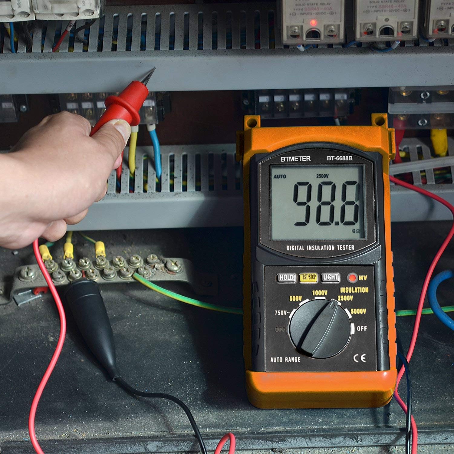
Figure 5.1: The AP-6688B being used to measure insulation resistance in an electrical panel.
5.2 AC Voltage Measurement
To measure AC voltage:
- Turn the rotary switch to the '750V AC' position.
- Connect the red and black test leads across the circuit or component where you want to measure AC voltage.
- The AC voltage reading will be displayed on the LCD.
5.3 Using the Backlight and Data Hold
- Backlight: Press the LIGHT button to turn the display backlight on or off. This is useful in dimly lit environments.
- Data Hold: Press the HOLD button to freeze the current reading on the display. Press it again to release the hold function and resume live readings.
6. Maintenance
6.1 Cleaning
- Wipe the meter's casing with a damp cloth and mild detergent. Do not use abrasive cleaners or solvents.
- Ensure the meter is completely dry before storage or next use.
6.2 Battery Replacement
When the battery indicator appears on the LCD, replace the batteries promptly to ensure accurate measurements. Refer to Section 4.2 for battery installation instructions.
6.3 Storage
- If the meter will not be used for an extended period, remove the batteries to prevent leakage and damage to the unit.
- Store the meter in a cool, dry place, away from direct sunlight and extreme temperatures.
- Use the provided carrying case to protect the meter from dust and physical damage.
7. Troubleshooting
| Problem | Possible Cause | Solution |
|---|---|---|
| Meter does not power on. | Dead or incorrectly installed batteries. | Check battery polarity; replace batteries. |
| Inaccurate readings. | Low battery; poor test lead connection; external interference. | Replace batteries; ensure secure connections; test in a clear environment. |
| HV indicator not lighting up during test. | Faulty unit; TEST/STOP button not pressed firmly. | Ensure button is fully pressed; contact support if issue persists. |
| Display is dim or flickering. | Low battery. | Replace batteries. |
8. Specifications
| Parameter | Value |
|---|---|
| Test Voltages | 500V, 1000V, 2500V, 5000V |
| Insulation Resistance Range | 1MΩ ~ 200GΩ |
| AC Voltage Range | 1V ~ 750V |
| Frequency Range | 40Hz ~ 400Hz |
| Display | 1999 Count LCD |
| Power Supply | 6 x 1.5V AA Batteries (Zinc-carbon) |
| Safety Standard | IEC 1010, Double Insulation, CAT II Overvoltage |
| Dimensions | 26.3 x 23.9 x 8.6 cm (approx.) |
| Weight | 900g (approx.) |
| Features | Auto Range, Data Hold, Backlight, HV Indicator |

Figure 8.1: Dimensions of the AP-6688B tester.
9. Warranty and Support
AOPUTTRIVER provides a 2-year warranty for the AP-6688B Digital Insulation Resistance Tester from the date of purchase. This warranty covers defects in materials and workmanship under normal use.
Additionally, AOPUTTRIVER offers lifetime technical support for this product. If you encounter any issues or have questions regarding the operation, maintenance, or troubleshooting of your AP-6688B, please do not hesitate to contact our customer support team.
For warranty claims or technical assistance, please refer to the contact information provided on our official website or the product packaging.


