1. Introduction
This manual provides instructions for the installation, operation, and maintenance of the JTS 9-inch Steamer Sight Glass Tube Replacement, Model UO-6190. This product is designed to replace existing sight glass tubes in boiler water level gauges, ensuring accurate water level monitoring. Please read these instructions carefully before proceeding with installation or use.
2. Product Components
The JTS Steamer Sight Glass Tube Replacement package includes the following components:
- One (1) 9-inch Sight Glass Tube
- Two (2) Rubber Washers/Gaskets
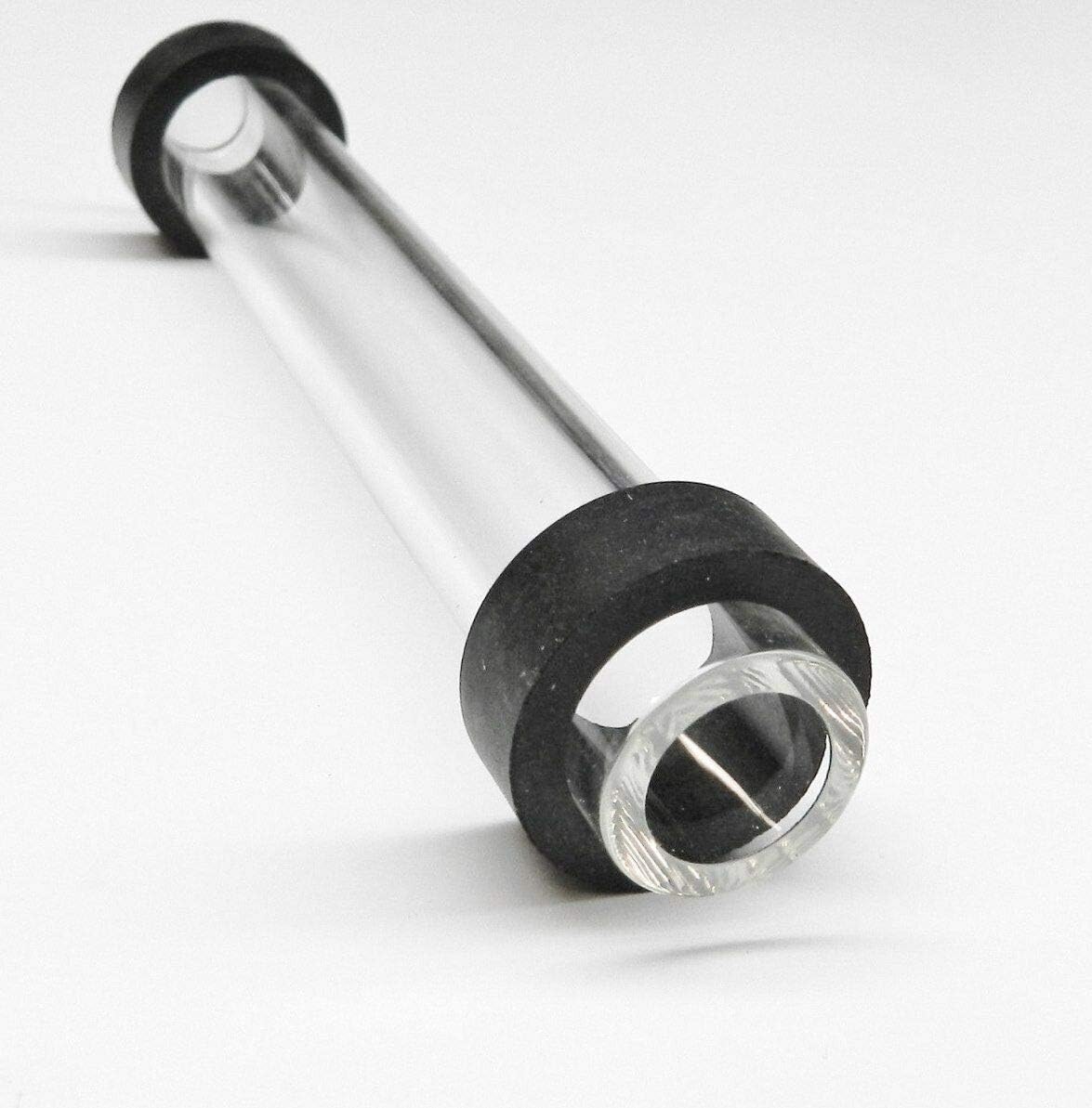
Figure 1: Assembled JTS 9-inch Steamer Sight Glass Tube with Washers.

Figure 2: The 9-inch Sight Glass Tube.

Figure 3: Two Rubber Washers/Gaskets.
3. Specifications
| Component | Measurement |
|---|---|
| Glass Tube Length | 9 inches |
| Glass Tube Outer Diameter (OD) | 5/8 inch |
| Glass Tube Inner Diameter (ID) | 3/8 inch |
| Rubber Washer Height | 3/8 inch |
| Rubber Washer Inner Diameter (ID) | 5/8 inch |
| JETS Product Numbers | 2115-6190 (Glass Tube), 2115-605 (Washers) |
| Manufacturing Origin | Made in USA |
4. Safety Information
WARNING: Boilers operate under high pressure and temperature. Improper installation or handling can result in serious injury or property damage. Always ensure the boiler system is depressurized and cooled before attempting any maintenance or replacement procedures. Consult a qualified technician if you are unsure about any steps.
- Always wear appropriate personal protective equipment (PPE), including safety glasses and heat-resistant gloves.
- Ensure the boiler is completely shut down, depressurized, and drained before beginning work.
- Verify that the replacement sight glass tube and washers match the specifications required by your boiler system.
- Do not overtighten fittings, as this can crack the glass tube.
- Inspect all components for damage before installation. Do not use damaged parts.
5. Installation Instructions (Replacement)
These instructions are for replacing an existing sight glass tube. Ensure all safety precautions are followed before beginning.
- Depressurize and Cool Boiler: Shut down the boiler system completely. Allow it to cool down to a safe temperature and ensure all pressure is relieved. Close all valves associated with the sight glass.
- Drain Sight Glass: Open the drain valve at the bottom of the sight glass assembly to drain any remaining water.
- Remove Old Components: Carefully loosen and remove the nuts or fittings holding the old sight glass tube in place. Remove the old tube and any old washers. Dispose of them properly.
- Clean Fittings: Thoroughly clean the internal surfaces of the sight glass fittings on the boiler to ensure a proper seal. Remove any scale or debris.
- Install New Washers: Place one new rubber washer onto each end of the new JTS sight glass tube. Ensure they are seated correctly.
- Insert New Tube: Carefully insert the new sight glass tube with washers into the boiler fittings. Ensure it is centered and aligned.
- Secure Fittings: Hand-tighten the nuts or fittings to secure the sight glass tube. Then, use a wrench to gently tighten them, alternating between the top and bottom fittings to apply even pressure. Do not overtighten. Overtightening can cause the glass to crack.
- Close Drain Valve: Close the drain valve at the bottom of the sight glass assembly.
- Pressurize and Check for Leaks: Slowly repressurize the boiler system. Carefully observe the sight glass and its connections for any signs of leaks. If leaks are detected, depressurize the boiler, tighten the fittings slightly, and recheck. If leaks persist, depressurize and inspect the washers and tube for damage or improper seating.
- Verify Water Level: Once the system is fully operational and leak-free, verify that the water level is clearly visible and accurate in the new sight glass.
6. Operation
The sight glass tube functions as a visual indicator of the water level within your boiler. Proper operation involves regular observation:
- Regular Monitoring: Periodically check the water level indicated by the sight glass. The water level should always be within the safe operating range specified by your boiler manufacturer.
- Clear Visibility: The glass tube should remain clear, allowing for an unobstructed view of the water level. If the glass becomes cloudy or discolored, it may require cleaning or replacement.
- False Level Indications: Be aware that rapid boiling or foaming within the boiler can sometimes create a "false" water level. Always cross-reference with other boiler level indicators if available.
7. Maintenance
Regular maintenance ensures the longevity and accuracy of your sight glass tube:
- Cleaning: If the sight glass becomes dirty or scaled, it may need to be cleaned. This typically involves depressurizing the boiler, draining the sight glass, and carefully cleaning the interior of the tube. For stubborn deposits, the tube may need to be removed and cleaned externally or replaced.
- Inspection: Periodically inspect the glass tube for cracks, chips, or etching. Inspect the rubber washers for signs of wear, hardening, or degradation. Replace any damaged components immediately.
- Washer Replacement: It is recommended to replace the rubber washers whenever the sight glass tube is removed or replaced, as they can harden and lose their sealing properties over time.
8. Troubleshooting
Common issues and their potential solutions:
- Leakage at Fittings:
- Ensure fittings are tightened evenly, but not overtightened.
- Check if washers are properly seated and not damaged. Replace if necessary.
- Inspect the glass tube for cracks near the fittings.
- Cloudy or Obscured View:
- The interior of the tube may have scale or deposits. Clean the tube as described in the Maintenance section.
- If cleaning does not resolve the issue, the glass may be etched and require replacement.
- Tube Cracks During Installation:
- This is often due to overtightening the fittings or uneven pressure. Ensure even tightening and avoid excessive force.
- Ensure the washers are correctly positioned to absorb pressure.
9. Manufacturer Information
This product is manufactured by JETS INC.
For further assistance or inquiries, please refer to the official JTS brand store or contact your supplier.
JETS Product Numbers:
- Glass Tube: 2115-6190
- Rubber Washers: 2115-605 (x2)


