1. Introduction
This user manual provides detailed instructions for the installation, operation, and maintenance of the POTTER 12/24 VDC 4-Wire Strobe Light, Model SL 5A C. This device is designed to provide visual signaling in various applications, particularly in fire safety and alarm systems. Please read this manual thoroughly before installation and operation to ensure proper function and safety.
2. Safety Information
Always adhere to local codes and regulations when installing and operating this device. Failure to do so may result in property damage, injury, or death.
- Disconnect all power sources before installation, maintenance, or servicing.
- Installation should only be performed by qualified personnel.
- Ensure proper wiring polarity and voltage (12/24 VDC) to prevent damage to the unit.
- Do not expose the device to excessive moisture or extreme temperatures outside its specified operating range.
- Regularly inspect the device for any signs of damage or wear.
3. Product Overview
The POTTER SL 5A C is a robust 12/24 VDC 4-wire cylindrical strobe light designed for clear visual signaling. It features a durable metal construction with a powder-coated finish and utilizes a Light Emitting Diode (LED) as its light source. Available in clear, red, orange, and yellow lens options.
3.1. Components
- Strobe Light Unit (Cylindrical Housing)
- Mounting Base
- Wiring Terminals (4-wire connection)
- Lens (Clear, Red, Orange, or Yellow)
3.2. Product Image
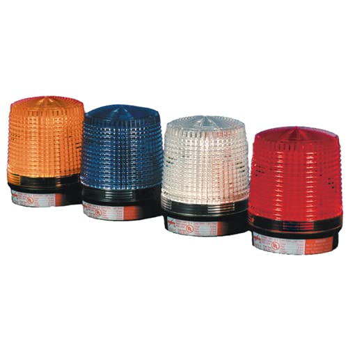
Image: A visual representation of four POTTER cylindrical strobe lights. From left to right, the lights are shown with orange, blue, clear, and red lenses. Each unit consists of a black base and a ribbed, translucent cylindrical lens, illustrating the design and color variations of the product line.
4. Setup and Installation
Follow these steps for proper installation of the POTTER SL 5A C strobe light:
- Power Disconnection: Ensure all power to the installation area is disconnected at the circuit breaker or fuse box before beginning any wiring.
- Mounting Location: Select a suitable mounting location that is stable, dry, and provides clear visibility for the strobe light. The device is designed for surface mounting.
- Mounting the Base: Secure the mounting base to the chosen surface using appropriate fasteners (not included). Ensure the base is firmly attached.
- Wiring: Connect the 4-wire power source to the terminals on the strobe light unit. Pay close attention to polarity (positive and negative) and ensure connections are secure. Refer to the wiring diagram provided with the product packaging for specific terminal assignments.
- Attach Strobe Unit: Once wiring is complete and verified, carefully attach the strobe light unit to its mounted base. Ensure it clicks or locks securely into place.
- Power Restoration: Restore power to the circuit and test the strobe light for proper operation.
5. Operating Instructions
The POTTER SL 5A C strobe light operates automatically when power is supplied to its 4-wire connection. It is designed to provide a continuous visual strobe signal when activated by the connected alarm or control panel.
- Activation: The strobe light will activate and begin flashing when the appropriate 12/24 VDC power is applied to its input terminals.
- Deactivation: The strobe light will cease flashing when the power supply is removed.
- Testing: Regular testing of the strobe light, in accordance with local fire safety regulations and system requirements, is recommended to ensure proper functionality.
6. Maintenance
The POTTER SL 5A C strobe light requires minimal maintenance. Regular inspection and cleaning will help ensure its longevity and reliable operation.
- Cleaning: Periodically clean the lens and exterior housing with a soft, damp cloth. Do not use abrasive cleaners or solvents, as these may damage the finish or lens.
- Inspection: Annually inspect the wiring connections for tightness and signs of corrosion. Check the mounting for security.
- Functionality Test: Perform regular functional tests as part of your overall fire alarm or security system maintenance schedule.
7. Troubleshooting
If the strobe light is not functioning as expected, refer to the following table for common issues and solutions:
| Problem | Possible Cause | Solution |
|---|---|---|
| Strobe light does not flash. | No power supply. Incorrect wiring/polarity. Faulty unit. | Verify power is supplied to the unit. Check all wiring connections for correctness and tightness, ensuring correct polarity. If power and wiring are correct, the unit may be faulty and require replacement. |
| Strobe light flashes intermittently. | Loose wiring connection. Insufficient power. | Check and tighten all wiring connections. Ensure the power supply is stable and within the 12/24 VDC range. |
| Light output is dim. | Dirty lens. Low voltage. | Clean the lens with a soft, damp cloth. Verify the input voltage is within the specified range (12/24 VDC). |
8. Specifications
| Feature | Detail |
|---|---|
| Model Number | SL 5A C |
| Part Number | PSL5AC |
| UPC | 742779300874 |
| Voltage | 12/24 VDC |
| Wiring | 4-Wire Connection |
| Light Source Type | Light Emitting Diode (LED) |
| Color Options | Clear, Red, Orange, Yellow (lens) |
| Shape | Cylindrical |
| Material | Metal |
| Finish Type | Powder Coated |
| Mounting Type | Surface Mount |
| Manufacturer | POTTER |
9. Warranty and Support
For information regarding the product warranty, please refer to the warranty card included with your purchase or visit the official POTTER website. For technical support, troubleshooting assistance beyond this manual, or replacement parts, please contact POTTER customer service through their official channels.
Note: Unauthorized modifications or repairs may void the product warranty.


