
1. Introduction
This manual provides instructions for the installation, operation, and maintenance of the Kunray 24-48V 350W Brushless Motor Controller with LCD Display, Model XCD-001. This controller kit is designed for electric bicycles, mountain bikes, scooters, dirt bikes, motorcycles, and mini bikes, offering precise speed control and comprehensive display functions.
2. Safety Information
- Ensure all connections are correct before powering on the system. Incorrect wiring, especially positive and negative poles, can cause damage.
- Always disconnect power before performing any installation, maintenance, or troubleshooting.
- The controller features undervoltage and overcurrent protection. Do not attempt to bypass these safety features.
- The LCD display is waterproof (IP65 rated), but avoid prolonged submersion.
- When performing the self-learning procedure, ensure the motor wheel is lifted off the ground to prevent unintended movement.
3. Product Overview
The Kunray XCD-001 controller kit includes a brushless motor controller and an S866 LCD display. The controller is designed with a grooved casing for efficient heat dissipation, ensuring stable performance and a long lifespan. The LCD display provides essential riding information and allows for various settings adjustments.
3.1 Controller Features
- Voltage Compatibility: 24V, 36V, 48V.
- Power Output: 350W.
- Current: 17A.
- Type: Brushless DC motor controller.
- Protection: Undervoltage protection, overcurrent protection, brake stop function.
- Heat Dissipation: Grooved design for effective thermal management.
- Material: Aluminum and Plastic.
3.2 LCD Display (S866) Features
- Real-time Data: Displays real-time speed, battery power, riding time, total mileage, and single trip mileage.
- Adjustable Settings: Allows adjustment of various parameters including speed, brightness, and assist levels.
- Durability: Waterproof (IP65 rated), backlit for visibility in various conditions, heat-resistant.
- User Interface: Intuitive buttons for quick operation.
- Handlebar Compatibility: Designed for handlebars with a 22mm diameter.

Figure 1: S866 LCD Display Functions Overview
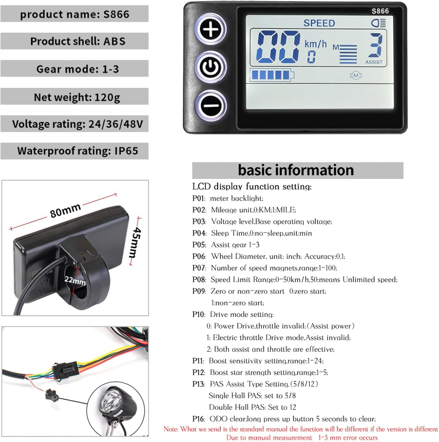
Figure 2: S866 LCD Display Basic Information and Dimensions

Figure 3: Controller Parameters and Dimensions
4. Specifications
| Feature | Detail |
|---|---|
| Product Dimensions (Controller) | 85 x 53 x 30 mm |
| Product Dimensions (LCD Display) | 80 x 45 mm |
| Controller Weight | Approx. 200 grams |
| LCD Display Weight | Approx. 120 grams |
| Voltage Rating | 24V / 36V / 48V |
| Power Output | 350W |
| Current | 17A |
| MOSFETs | 6 Mos |
| Controller Type | Brushless DC |
| Materials | Aluminum (Controller), ABS (Display Shell) |
| Waterproof Rating (Display) | IP65 |
| Handlebar Diameter (Display Mount) | 22 mm |
5. Setup and Installation
The controller and display feature clearly labeled interfaces for straightforward installation. Follow these steps carefully.
5.1 Wiring Diagram

Figure 4: Controller Wiring Diagram
Refer to the diagram above for connecting the various components to the controller. Ensure each connector is securely attached to its corresponding port. Key connections include:
- Battery: Connect the battery power wire (ensure correct polarity).
- Motor: Connect the motor phase wires and motor Hall wires.
- Display: Connect the display unit.
- Accelerator: Connect the throttle.
- Brake: Connect the brake levers.
- PAS Sensor: Connect the Pedal Assist System sensor.
- Self-Study Wires: Used for initial motor matching (see Section 5.3).
5.2 Product Installation Steps
- Connect the battery and motor:
- Connect the controller power wire to the battery. Caution: Be careful not to connect the positive and negative poles incorrectly.
- Connect the controller to the motor. The motor phase wire and the motor Hall wire should be connected one by one.
- Connect the controller to the instrument (LCD display).
After completing these steps, proceed to the self-learning procedure to match the motor.
- Self-learning (Motor Matching):
- Power on the meter (long press the power button of the meter for 3 seconds).
- Locate the two green self-learning wires on the controller and plug them into each other. Note: The motor will rotate after the self-learning wires are plugged in. Ensure the motor wheel is lifted off the ground beforehand to prevent speeding.
- Allow the motor to rotate for 10 to 20 seconds. If the motor rotates forward, the self-learning is complete. If the motor does not work, rotates in reverse, or makes noise, disconnect the self-learning wires, reconnect them, and the motor should rotate forward.
- After the motor rotates forward for 10 seconds, disconnect the two self-learning wires from each other. Do not turn off power or power off the display during this step.
After completing the self-learning, the motor matching is complete, and the test motor can be connected to the throttle.
Important: The self-learning wires should not remain connected after the self-learning process is complete. Disconnect them to prevent the motor from learning again when it starts next time.
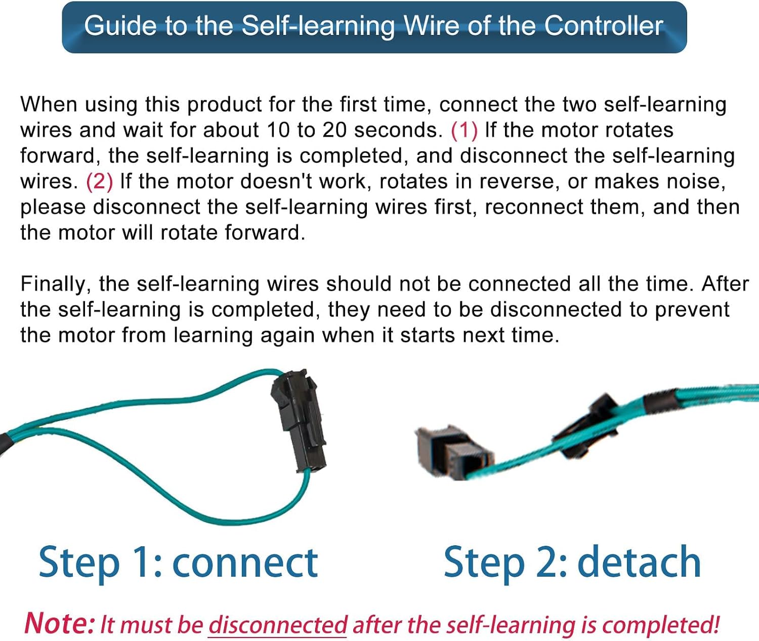
Figure 5: Self-Learning Wire Connection and Disconnection
For other functions, connect according to the definition of the controller socket. Unused functions can be left blank and cannot be wrongly connected.

Figure 6: Overview of Product Installation Steps
6. Operating Instructions (S866 LCD Display)
The S866 LCD display provides various functions and settings for your electric vehicle. The display is designed for easy operation with intuitive buttons.
6.1 Button Operation Guide

Figure 7: S866 LCD Display Button Functions
- Power On/Off: Press the Power button for 3 seconds to turn the meter on or off.
- Headlight Control: Press and hold the + button for 3 seconds to turn on/off the headlight power supply.
- Adjust Speed Gears: Short press the + or - button to add or subtract speed gears (assist levels).
- Enter/Exit Settings: Press the + and - buttons together for 3 seconds to enter or exit the setting interface. Press the Power button to select function item settings (range P01-P16). You can adjust corresponding function parameters using the + or - buttons.
- 6km/h Cruise: Long press the - button for 3 seconds to start or close the 6km/h cruise function.
Note: The "+" button is used to shift up, the "Power" button is ON/OFF, and the "-" button is used to shift down.
6.2 LCD Display Function Settings (P01-P16)
To access and modify these settings, enter the setting interface as described in step 4 of the Button Operation Guide.
- P01: Meter backlight brightness.
- P02: Mileage unit (0:KM; 1:MILE).
- P03: Voltage level (Base operating voltage).
- P04: Sleep time (No-sleep unit: min).
- P05: Assist gear (1-3).
- P06: Wheel Diameter unit (inch). Accuracy: 0.1.
- P07: Number of speed magnets (range: 1-100).
- P08: Speed Limit (Range: 0-50km/h, 50 means Unlimited speed).
- P09: Zero or non-zero start (0: zero start; 1: non-zero start).
- P10: Drive mode setting:
- 0: Power Drive (throttle invalid, assist power).
- 1: Electric throttle Drive mode (assist invalid).
- 2: Both assist and throttle are effective.
- P11: Boost sensitivity setting (range: 1-24).
- P12: Boost start strength setting (range: 1-5).
- P13: PAS Assist Type Setting (5/8/12).
- Single Hall PAS: set to 5/8.
- Double Hall PAS: set to 12.
- P16: ODO clear (long press up button 5 seconds to clear).
Note: What we send is the standard manual, the function will be different if the version is different. Due to manual measurement, 1-3 mm error occurs.
7. Maintenance
- Regularly check all wiring connections for tightness and signs of wear or damage.
- Keep the controller and display clean and free from dust and debris. Use a soft, dry cloth for cleaning.
- While the display is IP65 waterproof, avoid high-pressure washing or prolonged exposure to heavy rain.
- Do not attempt to open the controller casing, as this may void the warranty and expose internal components to damage.
- If any component is damaged, contact customer support for replacement parts or professional repair.
8. Troubleshooting
| Problem | Possible Cause | Solution |
|---|---|---|
| Motor does not run or runs in reverse after installation. | Incorrect self-learning procedure or wiring. | Repeat the self-learning procedure (Section 5.2). Ensure self-learning wires are disconnected after the process. Check motor phase and Hall sensor wiring. |
| Display does not power on. | Loose power connection, low battery, or faulty display. | Check battery charge. Ensure the display power cable is securely connected to the controller. Long press the power button for 3 seconds. |
| Inconsistent speed or power delivery. | Loose motor or Hall sensor connections, or incorrect P-settings. | Check all motor and Hall sensor connections. Verify P-settings (P05, P07, P08, P10, P11, P12, P13) on the LCD display. |
| Error code displayed on LCD. | System fault detected by the controller. | Consult the display's specific error code list (if available in a separate document) or contact customer support with the error code. Common issues include motor, Hall sensor, or brake faults. |
9. Warranty and Support
Kunray products are designed for durability and performance. This product comes with a standard warranty as per local regulations. For specific warranty details, please refer to your purchase documentation or contact the seller.
For technical support, troubleshooting assistance, or replacement parts, please contact Kunray Official customer service or your authorized dealer. When contacting support, please provide your product model (XCD-001) and a detailed description of the issue.
Manufacturer: Kunray Official
ASIN: B09KLPX4JL


