
1. Introduction
This manual provides detailed instructions for the installation, operation, and maintenance of the Taidacent Digital DC Resistance Measuring Instrument. This device is designed for accurate measurement of DC resistance within specified ranges.
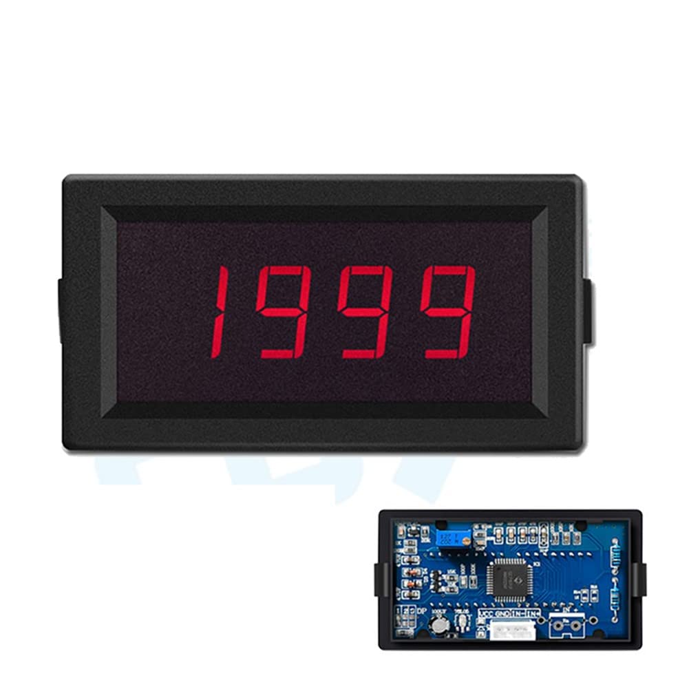
Figure 1: Front view of the Taidacent Ohm Meter. The display shows '1999' in red LED digits, indicating its digital output capability.
2. Safety Information and Precautions
- Power Supply: The instrument requires a DC5V or DC12V power supply (current consumption less than 50mA).
- Common Ground Instrument: This ohmmeter is a common ground instrument. It is non-isolated. It is strongly recommended to use a separate, independent, and isolated power supply for the meter. This means the power supply for the meter should not be connected to the signal measurement circuit to prevent damage or inaccurate readings.
- No Live Measurement: Do not measure resistance on circuits that are powered or "live". Measuring with electricity applied will damage the meter and may pose a safety risk. Ensure the circuit under test is completely de-energized before connecting the ohmmeter.
- Range Selection: Always select an appropriate measurement range. Selecting a range that is too high for a small resistance value may result in the resistance not being recognized or inaccurate measurements.
3. Product Overview and Components
The Taidacent Ohm Meter features a digital display for clear readings and a compact design for integration into various setups.

Figure 2: Back view of the Taidacent Ohm Meter. This image shows the rear casing and the connector port for power and signal input.
Key components include:
- Digital LED Display: 0.56 inches, red LED, displaying values from -1999 to 1999.
- Power Input: VCC (positive power), GND (ground).
- Signal Input: IN- (negative signal), IN+ (positive signal).
- Potentiometer: For fine-tuning and error adjustment.
- Decimal Point Jumper: For adjusting decimal point position.

Figure 3: Internal view of the meter's circuit board. Labels indicate the VCC (power supply), GND (ground), IN- and IN+ (signal input), a potentiometer for fine-tuning, and the decimal point adjustment jumper.
4. Setup and Installation
Follow these steps for proper installation and connection of your Taidacent Ohm Meter.
- Mounting: The meter has dimensions of 79x43x28mm. The recommended hole size for panel mounting is 76x39.5mm (±0.5~1mm). Ensure sufficient space for ventilation and connections.
- Power Connection: Connect the appropriate DC power supply (DC5V or DC12V) to the VCC (positive) and GND (negative) terminals. Remember to use a separate, isolated power supply for the meter as it is a common ground instrument.
- Signal Connection: Connect the resistance to be measured across the IN- and IN+ terminals. Ensure the circuit is completely de-energized before making connections.
- Wiring Diagram: Refer to the wiring diagram below for correct connections.
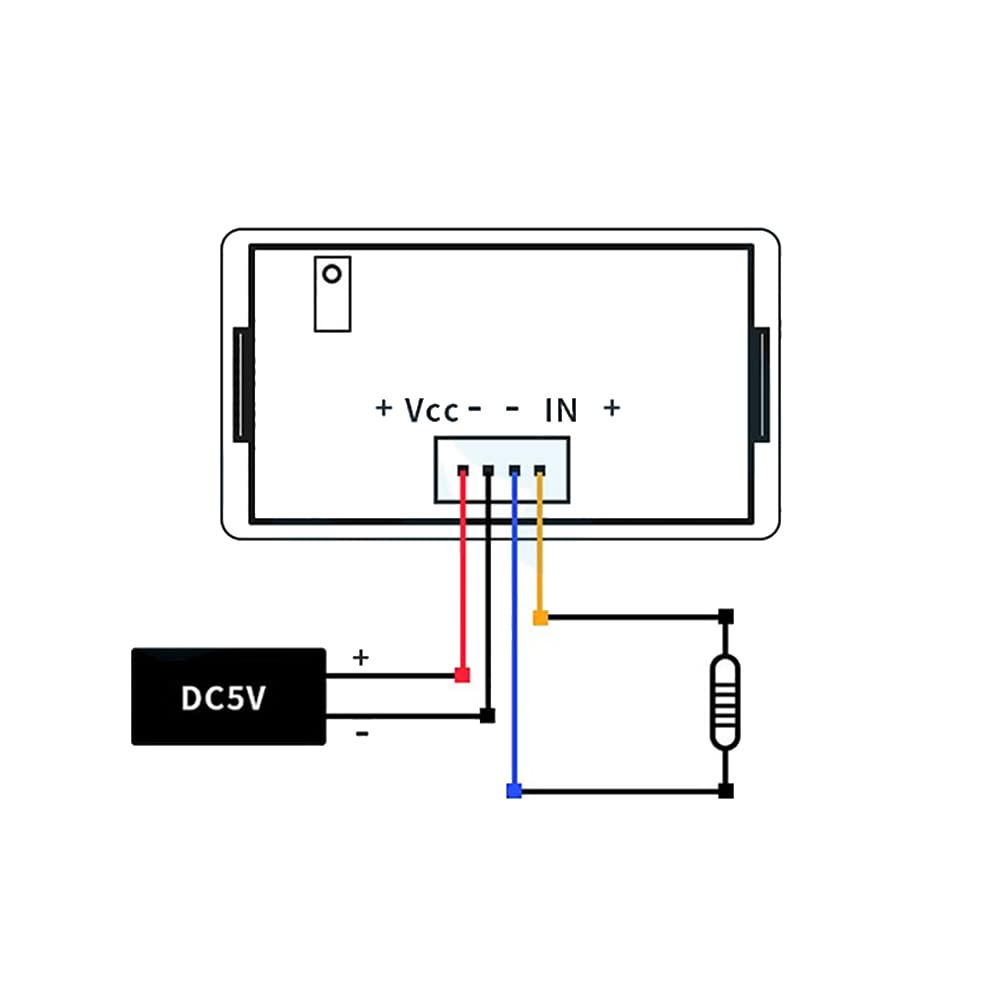
Figure 4: Wiring diagram illustrating how to connect the DC power supply (e.g., DC5V) to the VCC and GND terminals, and the resistance to be measured to the IN- and IN+ terminals.
5. Operating Instructions
To operate the Taidacent Ohm Meter, follow these guidelines:
- Power On: After ensuring all connections are correct and safe, apply power to the meter. The LED display will illuminate.
- Select Range: The meter automatically selects the range based on the input. However, for optimal accuracy, be aware of the available ranges and their resolutions:
- 200Ω Range: Display 0-199.9Ω, Resolution 100mΩ, Input Impedance 200Ω.
- 2KΩ Range: Display 0-1.999KΩ, Resolution 1Ω, Input Impedance 2KΩ. (For resistances above 200Ω and within 2KΩ, this range is used.)
- 20KΩ Range: Display 0-19.99KΩ, Resolution 10Ω, Input Impedance 20KΩ. (For resistances above 2KΩ and within 20KΩ, this range is used.)
- 200KΩ Range: Display 0-199.9KΩ, Resolution 100Ω, Input Impedance 200KΩ. (For resistances above 20KΩ and within 200KΩ, this range is used.)
Important: If the selected range is too high for the resistance being measured, the meter may not recognize the small resistance or provide inaccurate readings. Always ensure the resistance falls within the effective display range of the selected setting.
- Read Measurement: The resistance value will be displayed on the red LED screen.
- Fine-tuning (if necessary): If calibration is required, use the potentiometer on the circuit board (refer to Figure 3) for fine-tuning and error adjustment.
6. Maintenance
The Taidacent Ohm Meter is designed for reliable operation with minimal maintenance. Follow these general guidelines:
- Cleaning: Keep the instrument clean and free from dust and debris. Use a soft, dry cloth for cleaning. Do not use abrasive cleaners or solvents.
- Storage: Store the meter in a dry environment, away from extreme temperatures and direct sunlight.
- Inspection: Periodically inspect the wiring and connections for any signs of wear or damage.
7. Troubleshooting
If you encounter issues with your Taidacent Ohm Meter, consider the following:
- No Display/Incorrect Reading:
- Check power supply connections (VCC, GND) and ensure the correct voltage (DC5V or DC12V) is applied.
- Verify that a separate, isolated power supply is being used for the meter.
- Ensure the resistance being measured is within the meter's specified range.
- Confirm that the circuit under test is de-energized. Measuring live circuits will damage the meter.
- Check signal connections (IN-, IN+) for proper contact.
- Inaccurate Readings:
- Ensure the correct measurement range is being used for the resistance value.
- Check for any loose connections or damaged wiring.
- Consider environmental factors such as temperature and humidity, though the meter is designed for 0-50℃ and 80%RH.
- If persistent, fine-tune the meter using the potentiometer (refer to Figure 3).
- Meter Damage: If the meter was connected to a live circuit, it is likely damaged and may require replacement.
8. Specifications
| Parameter | Value |
|---|---|
| Power Supply | DC5V / DC12V (optional) |
| Current Consumption | Less than 50mA |
| Display Range | -1999 ~ 1999 |
| Font Size | 0.56 inches red LED |
| Measurement Accuracy | 0.5 level ± 2 words |
| Temperature Drift Coefficient | Less than 100PPM/°C |
| Working Environment | 0-50°C; 80%RH |
| Dimensions (L x W x H) | 79mm x 43mm x 28mm |
| Hole Size for Mounting | 76mm x 39.5mm (±0.5~1mm) |
| Package Type | Flat right-angle frame, purple frosted window |
Resistance Measurement Ranges:
| Range | Display Range | Resolution | Input Impedance |
|---|---|---|---|
| 200Ω | 0 - 199.9Ω | 100mΩ | 200Ω |
| 2KΩ | 0 - 1.999KΩ | 1Ω | 2KΩ |
| 20KΩ | 0 - 19.99KΩ | 10Ω | 20KΩ |
| 200KΩ | 0 - 199.9KΩ | 100Ω | 200KΩ |
9. Warranty and Support
For warranty information and technical support, please refer to the documentation provided with your purchase or contact your retailer or the manufacturer directly. Keep your purchase receipt as proof of purchase.