1. Introduction
This manual provides essential information for the proper installation, operation, and maintenance of your DB Electrical 245-12160 Solenoid. Please read these instructions carefully before proceeding with installation or use to ensure safety and optimal performance of the product.
2. Product Specifications
The DB Electrical 245-12160 Solenoid is designed as a replacement component for various applications, including tractors. Key specifications are as follows:
- Quality Type: Standard
- Voltage: 12 Volt
- Duty Cycle: Intermittent
- Contact Material: Copper
- Number of Terminals: 4
- Special Note: Features a molded extension for arc protection. The "R" terminal is a dummy terminal and is electrically non-functional.
- Product Dimensions: 2.5 x 7 x 2.5 inches
- Item Weight: 2.75 pounds
This solenoid replaces OEM numbers including ARROWHEAD: 245-12160, SNK6013, ZM808; DELCO: 10457061; J&N ELECTRICAL PRODUCTS: 245-12088, 245-12135, 245-12161; NIKKO: 0-47100-4279, 0-47100-4310; ZM Solenoids: ZM808.

Image 1: The DB Electrical 245-12160 Solenoid. This image shows the overall appearance of the solenoid, including its metallic body and terminal connections.
3. Safety Information
Always observe the following safety precautions when working with electrical components:
- Disconnect the vehicle's battery before beginning any electrical work to prevent accidental shorts or injury.
- Wear appropriate personal protective equipment, including safety glasses and gloves.
- Ensure all connections are clean, tight, and free from corrosion.
- Do not attempt to modify the solenoid.
- If you are unsure about any step, consult a qualified technician.
4. Installation Instructions
Follow these steps for proper installation of the solenoid:
- Preparation: Ensure the vehicle's battery is disconnected. Locate the existing solenoid and note its connections.
- Removal: Carefully disconnect all wires from the old solenoid. Remove the mounting bolts and detach the old solenoid.
- Terminal Identification: Refer to the terminal diagram below for correct identification of the new solenoid's terminals.
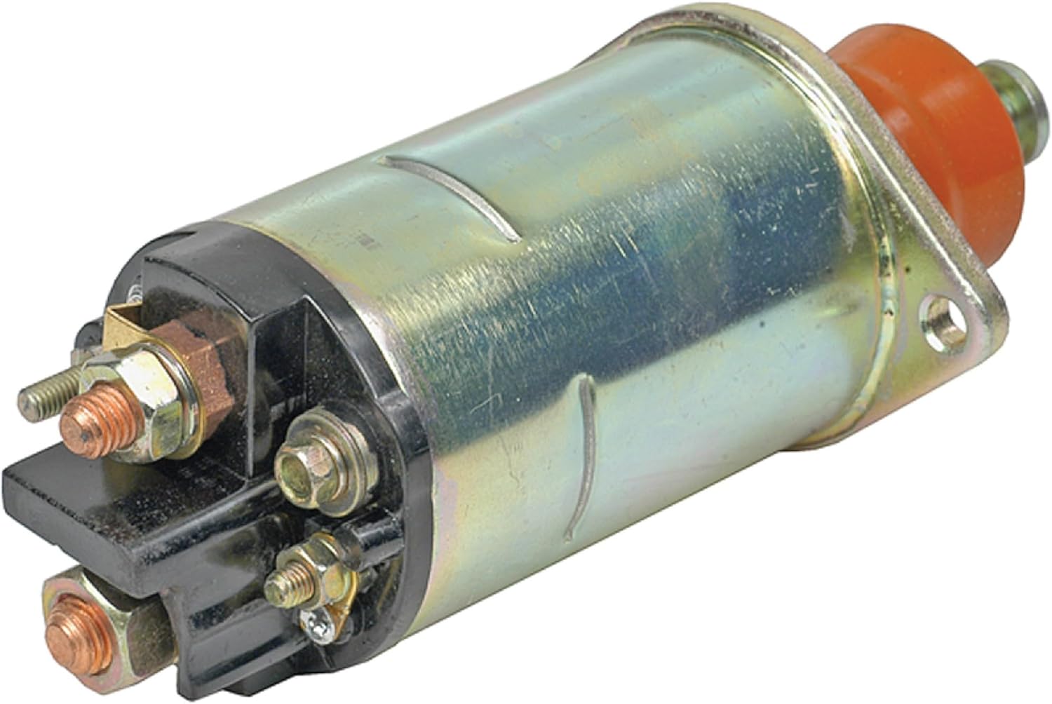
Image 2: Solenoid Terminal Diagram. This diagram illustrates the four terminals: BAT (M10-1.5), MTR (M8-1.25), S (M5-0.8), and R (M5-0.8). Note that the 'R' terminal is a dummy and non-functional.
- Mounting: Position the new DB Electrical 245-12160 Solenoid in the correct location and secure it with the appropriate mounting hardware.
- Wiring Connections: Connect the wires to the corresponding terminals on the new solenoid. Ensure all connections are secure and tight.
- BAT (Battery) Terminal (M10-1.5): Connect the main battery cable.
- MTR (Motor) Terminal (M8-1.25): Connect the cable leading to the starter motor.
- S (Switch/Start) Terminal (M5-0.8): Connect the ignition switch wire (small gauge).
- R (Resistor/Ignition) Terminal (M5-0.8): This is a dummy terminal and should not be connected to any active circuit. It is electrically non-functional.
- Final Check: Double-check all connections for correctness and tightness.
- Reconnect Battery: Reconnect the vehicle's battery.
- Test: Test the starter system to ensure proper operation.
5. Operation
The solenoid acts as an electromagnetic switch. When the ignition key is turned to the 'start' position, a small current flows to the 'S' terminal, energizing the solenoid. This creates a magnetic field that pulls a plunger, closing the heavy-duty contacts between the 'BAT' and 'MTR' terminals. This allows a large current to flow from the battery to the starter motor, engaging the starter and cranking the engine. Once the engine starts and the key is released, the solenoid de-energizes, opening the contacts and disengaging the starter.
6. Maintenance
The DB Electrical 245-12160 Solenoid is designed for durability and requires minimal maintenance. However, periodic checks can help ensure its longevity:
- Inspect Connections: Regularly check all terminal connections for tightness and corrosion. Loose or corroded connections can lead to poor performance or failure.
- Cleanliness: Keep the solenoid free from excessive dirt, oil, and moisture.
- Visual Inspection: Look for any signs of physical damage, such as cracks or melted plastic, which may indicate overheating or electrical issues.
7. Troubleshooting
If you experience issues with your starter system, consider the following common troubleshooting steps related to the solenoid:
- Engine Does Not Crank (Clicking Sound): This often indicates a weak battery, poor battery cable connections, or a faulty solenoid. Check battery voltage and terminal connections first. If the solenoid clicks but the starter doesn't engage, the solenoid contacts might be worn or stuck.
- Engine Does Not Crank (No Sound): This could be due to a completely dead battery, a faulty ignition switch, an open circuit to the 'S' terminal, or a completely failed solenoid. Verify power to the 'S' terminal when the key is turned to start.
- Solenoid Stays Engaged: This is rare but can happen if the solenoid contacts weld together or if the ignition switch is faulty and continuously sends power to the 'S' terminal. Disconnect the battery immediately if this occurs.
Always ensure the battery is fully charged and its connections are clean and tight before diagnosing solenoid issues.
8. Warranty Information
Your DB Electrical 245-12160 Solenoid is covered by a 1-year warranty from the date of purchase. This warranty protects against manufacturing defects and ensures that the product will function as intended when properly installed. If you encounter any issues within this period, please contact DB Electrical for assistance or a replacement.
9. Support
For further assistance, technical support, or warranty claims, please refer to the contact information provided with your purchase or visit the official DB Electrical website. When contacting support, please have your product model number (245-12160) and purchase details readily available.


