
1. Introduction
The VPFET HDMI Extender Splitter (Model EX60H-712) is designed to distribute one HDMI source signal to two identical HDMI outputs over Cat5e or Cat6 Ethernet cables. It supports resolutions up to 1080p@60Hz and extends signals up to 165 feet (50 meters). This device also features two local HDMI loop-out ports on the transmitter unit, allowing for local display monitoring. Power over Cable (PoC) technology simplifies installation by powering the receiver units from the transmitter.
2. Product Features
- HDMI Extender Splitter Functionality: Splits one HDMI signal into two identical signals for transmission over Cat5e/6 cable.
- Extended Range: Transmits HDMI signals up to 165 feet (50 meters) using Cat6/7 cable, 130 feet (40 meters) using Cat5e, and 100 feet (30 meters) using Cat5.
- Local Loop-Out: Includes two HDMI loop-out ports on the transmitter for connecting local displays.
- Power over Cable (PoC): Receiver units are powered via the Ethernet cable from the transmitter, requiring only one power adapter at the transmitter.
- EDID Management: Supports various EDID preset programs to enhance compatibility between source and display devices.
- High Resolution Support: Supports resolutions up to 1920x1200@60Hz and 1080p@60Hz.
- Audio Format Support: Compatible with PCM, DTS, and DSD audio formats.
- Automatic Equalization (Auto EQ): Built-in chip automatically adjusts equalization settings for optimal signal quality over varying cable lengths.
- Plug and Play: No software installation required for setup.
3. Package Contents
Verify that all items are present in your package:
- 1x HDMI Extender Splitter Transmitter (TX)
- 2x HDMI Extender Receiver (RX)
- 1x DC 12V Power Adapter
- 1x Pair of Fixed Hangers
- 1x User Manual
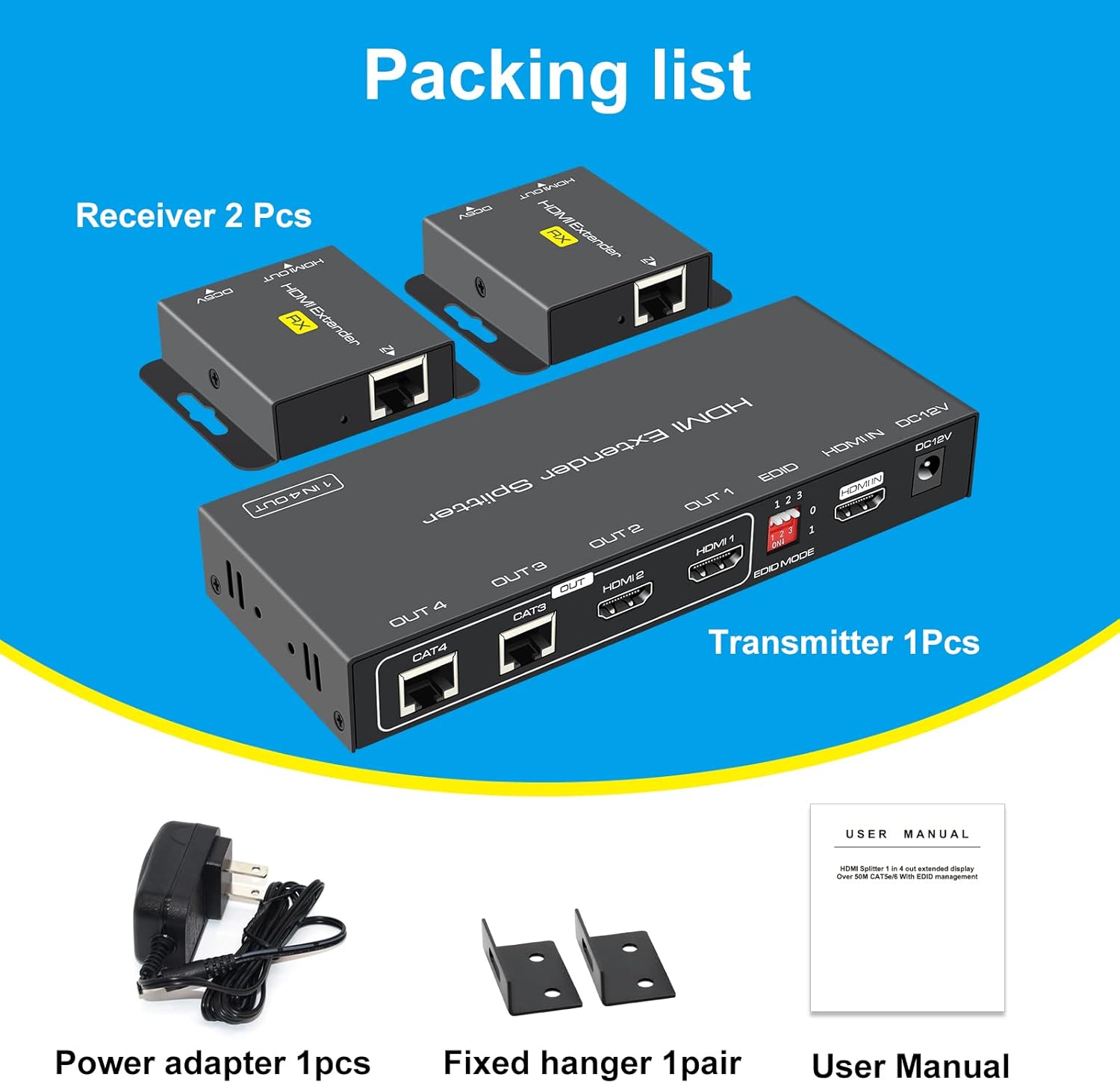
Image: Contents of the VPFET HDMI Extender Splitter package.
4. Product Components
4.1 Transmitter (TX) Front Panel

Image: Front and Rear Panel of the Transmitter unit.
- ON/OFF Switch: Power switch for the transmitter unit.
- Power Indicator: LED light indicating power status.
- HDMI Input Indicator: LED light indicating an active HDMI input signal.
4.2 Transmitter (TX) Rear Panel
- RJ45 Outputs (CAT3, CAT4): Connect to the receiver units via Cat5e/6 Ethernet cables.
- HDMI Outputs (HDMI1, HDMI2): Local HDMI loop-out ports for connecting local displays.
- EDID Switch: DIP switch for selecting EDID modes.
- HDMI Input: Connects to the HDMI source device.
- DC 12V Power Input: Connect the provided 12V power adapter here.
4.3 Receiver (RX) Unit
Each receiver unit has an RJ45 input to connect to the transmitter and an HDMI output to connect to a display. It also has a DC 5V input, but typically receives power via PoC from the transmitter.
5. Setup Instructions
Follow these steps to set up your HDMI Extender Splitter:
- Prepare Cables: Ensure you have appropriate HDMI cables for source and local displays, and Cat5e/6 Ethernet cables (up to 165ft/50m) for connecting to remote displays. Use TIA/EIA 568B wiring standard for Ethernet cables.
- Connect HDMI Source: Connect your HDMI source device (e.g., laptop, PC, DVD player) to the HDMI IN port on the Transmitter (TX) unit using an HDMI cable.
- Connect Local Displays (Optional): If you wish to have local displays, connect them to the HDMI1 and HDMI2 loop-out ports on the Transmitter (TX) unit using HDMI cables.
- Connect Ethernet Cables: Connect Cat5e/6 Ethernet cables from the CAT3 and CAT4 ports on the Transmitter (TX) unit to the RJ45 input ports on the two Receiver (RX) units.
- Connect Remote Displays: Connect each Receiver (RX) unit's HDMI output to your remote display devices using HDMI cables.
- Connect Power: Connect the provided 12V DC power adapter to the DC 12V input port on the Transmitter (TX) unit. The receiver units will be powered via the Ethernet cables (PoC).
- Power On: Turn on the HDMI Extender Splitter using the ON/OFF switch on the transmitter. Then, power on your HDMI source and all connected displays.

Image: Typical wiring diagram for the HDMI Extender Splitter.

Image: Example application scenario with local and remote displays.
5.1 RJ45 Pinout (TIA/EIA 568B Standard)
For optimal performance, ensure your Cat5e/6 cables are wired according to the TIA/EIA 568B standard:
- Pin 1: Orange/White
- Pin 2: Orange
- Pin 3: Green/White
- Pin 4: Blue
- Pin 5: Blue/White
- Pin 6: Green
- Pin 7: Brown/White
- Pin 8: Brown

Image: RJ45 Pinout (TIA/EIA 568B).
6. Operating Instructions
Once all connections are made and devices are powered on, the HDMI signal from your source will be automatically distributed to the local loop-out displays and the remote displays connected via the receiver units. The system operates on a plug-and-play basis, requiring no additional software or complex configuration for basic functionality.
6.1 EDID Settings
The EDID (Extended Display Identification Data) switch on the transmitter allows you to select different display modes to ensure compatibility with various source and display devices. Adjust the DIP switches (1, 2, 3) according to the desired resolution and audio channel configuration.
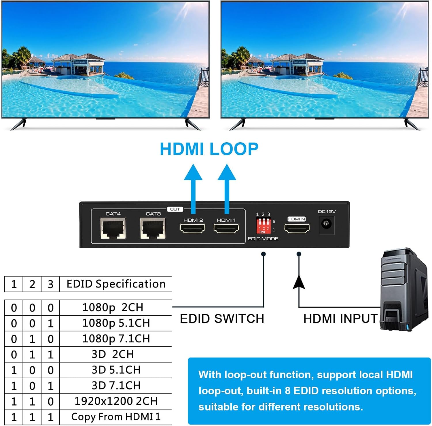
Image: EDID switch settings and their corresponding specifications.
| DIP Switch 1 | DIP Switch 2 | DIP Switch 3 | EDID Specification |
|---|---|---|---|
| 0 | 0 | 0 | 1080p 2CH |
| 0 | 0 | 1 | 1080p 5.1CH |
| 0 | 1 | 0 | 1080p 7.1CH |
| 0 | 1 | 1 | 3D 2CH |
| 1 | 0 | 0 | 3D 5.1CH |
| 1 | 0 | 1 | 3D 7.1CH |
| 1 | 1 | 0 | 1920x1200 2CH |
| 1 | 1 | 1 | Copy From HDMI 1 |
Note: '0' typically means the switch is in the 'OFF' or 'down' position, and '1' means 'ON' or 'up'. Refer to the physical switch markings for exact interpretation.
6.2 Power over Cable (PoC)
This extender utilizes PoC technology, meaning the receiver units draw power directly from the transmitter via the Ethernet cable. This eliminates the need for separate power adapters at the receiver locations, simplifying installation and reducing cable clutter.
Important: The 12V power adapter MUST be connected to the Transmitter (TX) unit. Connecting it to a receiver unit or using an incorrect voltage may damage the device.

Image: Power over Cable (PoC) functionality.
7. Specifications
| Feature | Specification |
|---|---|
| Model Number | EX60H-712 |
| HDMI Compliance | HDCP Compliant |
| Supported Resolutions | Up to 1920x1200@60Hz, 1080p@60Hz |
| Audio Formats | PCM, DTS, DSD |
| Transmission Distance (Cat6/7) | Up to 165 ft (50 m) |
| Transmission Distance (Cat5e) | Up to 130 ft (40 m) |
| Transmission Distance (Cat5) | Up to 100 ft (30 m) |
| Power Supply | DC 12V (for Transmitter) |
| Power Consumption | Not specified (low power) |
| Operating Temperature | Not specified |
| Product Dimensions (TX) | Approx. 0.31 x 0.16 x 0.08 inches (L x W x H) |
| Item Weight | 9.5 ounces |
| Color | Black |
8. Troubleshooting
If you encounter issues with your HDMI Extender Splitter, refer to the following common problems and solutions:
- No Picture on Display:
- Ensure all HDMI and Ethernet cables are securely connected.
- Verify the 12V power adapter is correctly connected to the Transmitter (TX) unit and the unit is powered on.
- Check if the HDMI source device and displays are powered on and set to the correct input.
- Try a different HDMI cable between the source and transmitter, or between the receiver and display.
- Test with a shorter Ethernet cable to rule out cable length issues.
- Adjust the EDID switch settings on the transmitter to match the capabilities of your display.
- If using a very old or specific TV, an additional HDMI buffer/amplifier or EDID manager might be required for local loop-out ports.
- Poor Picture Quality or Flickering:
- Ensure you are using high-quality Cat5e/6 cables, preferably Cat6 or Cat7 for longer distances.
- Verify the Ethernet cables are wired correctly (TIA/EIA 568B standard).
- Reduce the length of the Ethernet cable if it exceeds recommended limits.
- Check for strong electromagnetic interference (EMI) near the cables.
- Try adjusting the EDID settings to a lower resolution if the issue persists.
- No Audio:
- Ensure your display's audio is not muted or set to a very low volume.
- Check the audio settings on your HDMI source device.
- Verify the EDID switch settings support the desired audio format (e.g., 2CH, 5.1CH, 7.1CH).
- Receivers Not Powering On (No PoC):
- Confirm the 12V power adapter is connected to the Transmitter (TX) unit.
- Ensure the Ethernet cables are properly connected and not damaged.
- Test the Ethernet cables with a cable tester to confirm continuity and correct wiring.
9. Safety Information
- Do not expose this device to water, moisture, or excessive humidity.
- Do not attempt to open or repair the device yourself. Refer all servicing to qualified personnel.
- Use only the provided 12V DC power adapter. Using an incorrect power supply may damage the device and void the warranty.
- Place the device in a well-ventilated area to prevent overheating.
- Keep the device away from heat sources, direct sunlight, and strong magnetic fields.
- Clean the device with a soft, dry cloth. Do not use liquid or aerosol cleaners.
10. Official Product Video
Watch this official video for a visual guide on the VPFET HDMI Extender Splitter 1 in 2 Out:
Video: An overview and demonstration of the VPFET HDMI Extender Splitter 1 in 2 Out, showcasing its features and connectivity.
11. Warranty and Support
VPFET products are designed for reliability and performance. This product comes with a standard manufacturer's warranty. For specific warranty details, technical support, or customer service inquiries, please refer to the contact information provided with your purchase or visit the official VPFET website.
You can visit the VPFET Store for more products and information: VPFET Store on Amazon