
Anern 30A PWM Solar Charge Controller
Anern 30A PWM Solar Charge Controller User Manual
Intelligent Regulator with Adjustable LCD, Dual USB Ports, Auto Timer Settings, Multiple Load Control Modes
1. Product Overview
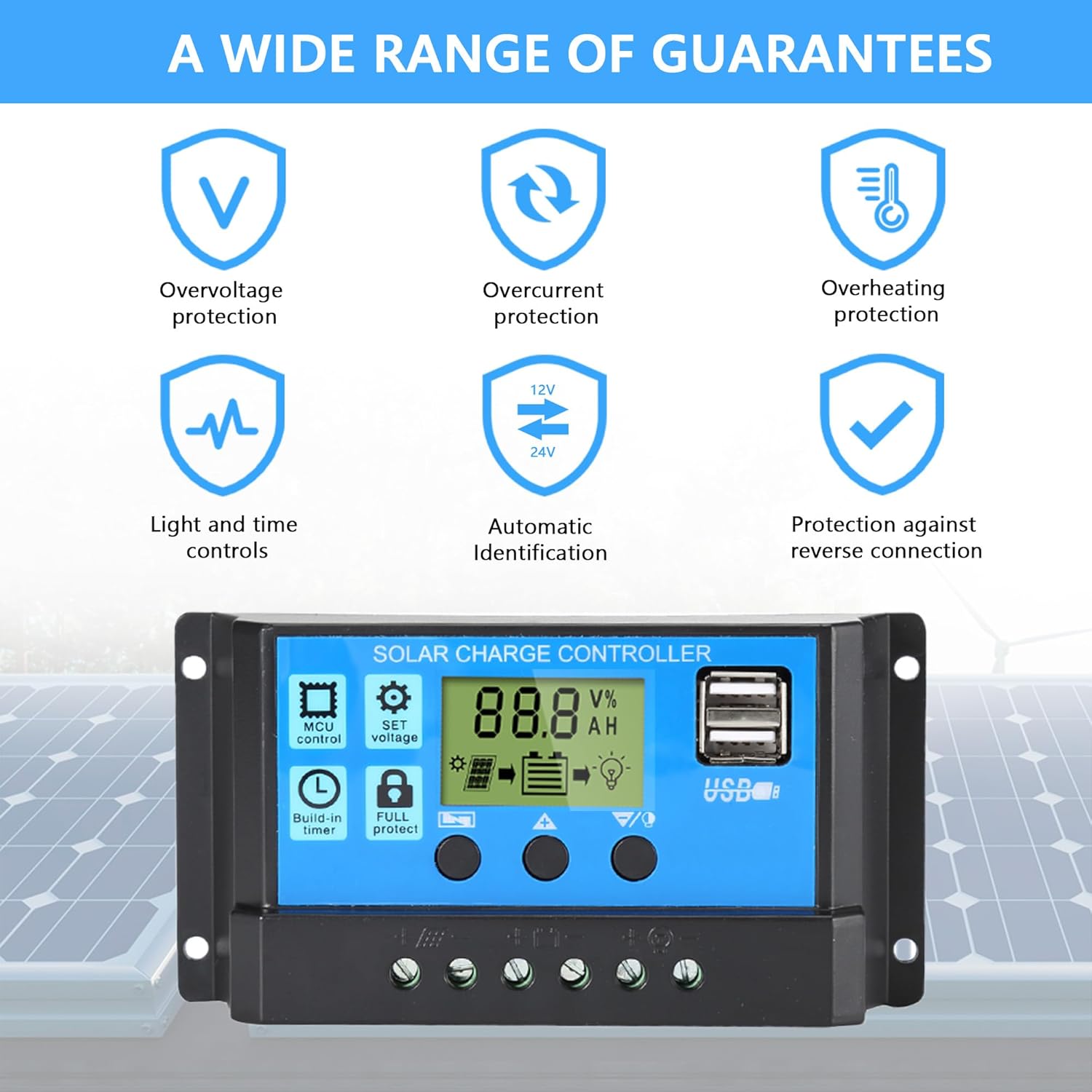
The Anern 30A PWM Solar Charge Controller is designed to manage the power flow from your solar panels to your battery bank, ensuring efficient and safe charging. It features a full 3-stage PWM charge management system, an intuitive LCD display, and multiple protection functions. This controller is suitable for 12V/24V systems and is equipped with dual USB ports for charging external devices.

2. Safety Precautions
- Ensure all connections are correct before connecting the battery or solar panels.
- This controller is designed for lead-acid batteries only (OPEN, AGM, GEL). Do not use with nickel-hydride, lithium, Li-ion, or other battery types.
- Install the controller in a well-ventilated area, away from flammable materials.
- Avoid direct sunlight and moisture exposure.
- Always connect the battery first, then the solar panel, and finally the load. Disconnect in the reverse order.
- Ensure proper wire gauge is used for connections to prevent overheating.
3. Setup Guide
3.1. Connection Order
- Connect the battery to the charge controller. Ensure correct polarity (+ to + and - to -). The controller will detect the battery voltage (12V or 24V) automatically.
- Connect the solar panel(s) to the charge controller. Ensure correct polarity.
- Connect the DC load to the charge controller (if applicable). Ensure correct polarity.
Important: Always follow this connection order to prevent damage to the controller or other components. Disconnect in the reverse order: Load → Solar Panel → Battery.

4. Operating Instructions
4.1. LCD Display and Buttons
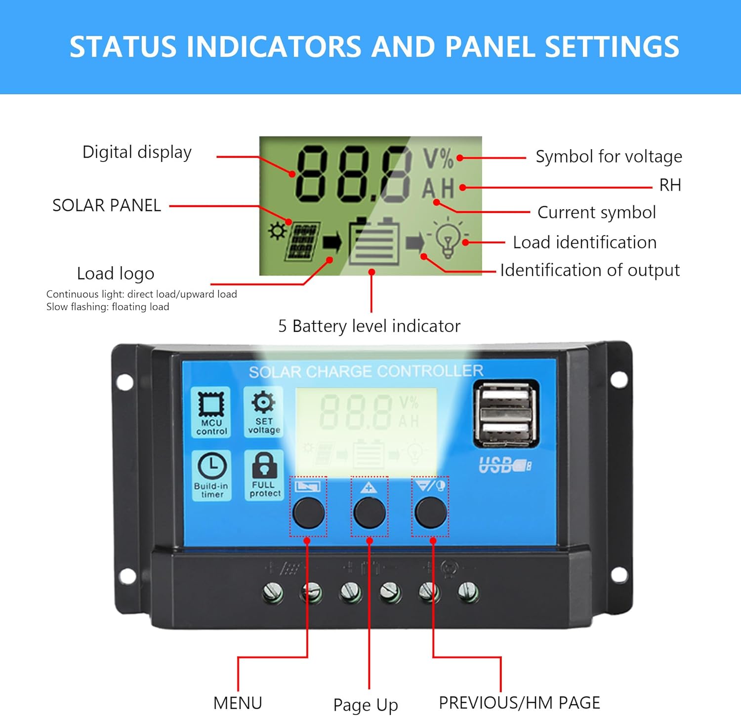
The controller features an intuitive LCD display that shows real-time status and data. There are three buttons for navigation and parameter settings:
- MENU: Press to browse different display interfaces. Long press to enter/exit settings.
- UP: Press to increase values in settings.
- DOWN/HM: Press to decrease values in settings.
4.2. Parameter Settings
To adjust parameters:
- Long press the MENU button for 5 seconds to enter the setting mode. The current parameter value will flash.
- Use the UP and DOWN/HM buttons to adjust the value.
- Press the MENU button again to save the setting and move to the next parameter, or long press MENU for 5 seconds to exit settings.
The controller allows adjustment of various parameters, including:
- Floating Voltage: The voltage at which the battery is maintained after reaching full charge.
- Discharge Switch-off Voltage: The voltage at which the load output is disconnected to protect the battery from over-discharge.
- Discharge Reconnection Voltage: The voltage at which the load output is reconnected after being disconnected due to low battery.
- Battery Type: Ensure this matches your connected lead-acid battery (OPEN, AGM, GEL).
- Working Modes: Configure load control modes (e.g., 24H for continuous output, or timer settings for dusk-to-dawn operation).

4.3. USB Charging
The dual 5V/2A USB ports can be used to charge mobile phones or other 5-voltage devices. These ports provide convenient power for small electronics directly from your solar system.
5. Maintenance
Regular maintenance ensures optimal performance and longevity of your solar charge controller:
- Cleaning: Periodically clean the controller's exterior with a dry cloth to remove dust and debris. Ensure ventilation openings are clear.
- Connection Check: Annually inspect all wiring connections for tightness and corrosion. Loose connections can lead to power loss or overheating.
- Environment: Ensure the installation environment remains within the specified operating temperature range and is free from excessive moisture or dust.
- Battery Health: Monitor your battery's health and ensure it is suitable for use with the controller.
6. Troubleshooting
This section addresses common issues you might encounter:
- Controller Not Turning On: Check battery connections and ensure correct polarity. The controller requires battery power to operate.
- Battery Not Charging: Verify solar panel connections and ensure they are receiving sufficient sunlight. Check for any shading or damage to panels. Confirm battery type setting is correct.
- Load Not Working: Check load connections and ensure the load is within the controller's rated current. Verify load working mode settings (e.g., 24H, timer). The controller has built-in overcurrent protection for the load.
- Display Errors: If the display shows unusual readings or error codes, first check all connections. Disconnect and reconnect the battery (following the correct order) to reset the controller.
- Over-discharge Protection: If the battery voltage drops too low, the controller will disconnect the load to protect the battery. The load will reconnect once the battery voltage recovers.
- Overcharge Protection: The controller automatically stops charging when the battery reaches full capacity, preventing overcharging.
7. Technical Specifications
| Feature | Specification |
|---|---|
| Brand | Anern |
| Model | 30A PWM Solar Charge Controller |
| Voltage | 12V/24V Auto-sensing |
| Max Charge Current | 30A |
| Display Type | LCD |
| Charging Port Type | Dual USB (5V/2A) |
| Operating Temperature | -20°C to +60°C (approx. 6E+1 Degrees Celsius is 60 degrees C) |
| Product Dimensions | 1.18"L x 2.76"W x 5.24"H (30 x 70 x 133 mm) |
| Item Weight | 4.2 ounces (119 grams) |
| Material | Acrylonitrile Butadiene Styrene (ABS) |
| Compatible Battery Types | OPEN, AGM, GEL Lead-acid batteries |
8. Warranty and Support
Anern offers a one-year maintenance service for this solar charge controller. If there is a problem with the components of the controller within this period, Anern will provide replacement components.
For technical support or warranty claims, please contact Anern customer service through the platform where you purchased the product or visit the official Anern store page on Amazon: Anern Store.
Ask a question about this manual
Ask about setup, troubleshooting, compatibility, parts, safety, or missing instructions. Manuals+ will review the question and use this page’s manual context to help answer it.