1. Introduction
This manual provides detailed instructions for the Teyleten Robot PH Value Data Detection and Acquisition Sensor Module, Model DB7. This module is designed for measuring pH levels in various applications, offering an analog voltage signal output for integration with microcontrollers like Arduino. It is suitable for monitoring acidity and alkalinity within a pH range of 0-14 and a temperature range of 0-80°C.
2. Product Overview and Components
The Teyleten Robot PH Sensor Module consists of a pH electrode probe and a signal acquisition board. The pH electrode features a BNC connector for reliable attachment to the module. The module itself provides an analog output signal proportional to the pH value.

Image 2.1: Complete Teyleten Robot PH Sensor Module kit, including the pH probe, sensor board, and mounting hardware.

Image 2.2: Close-up of the sensor module and included mounting hardware (screws, nuts, washers).
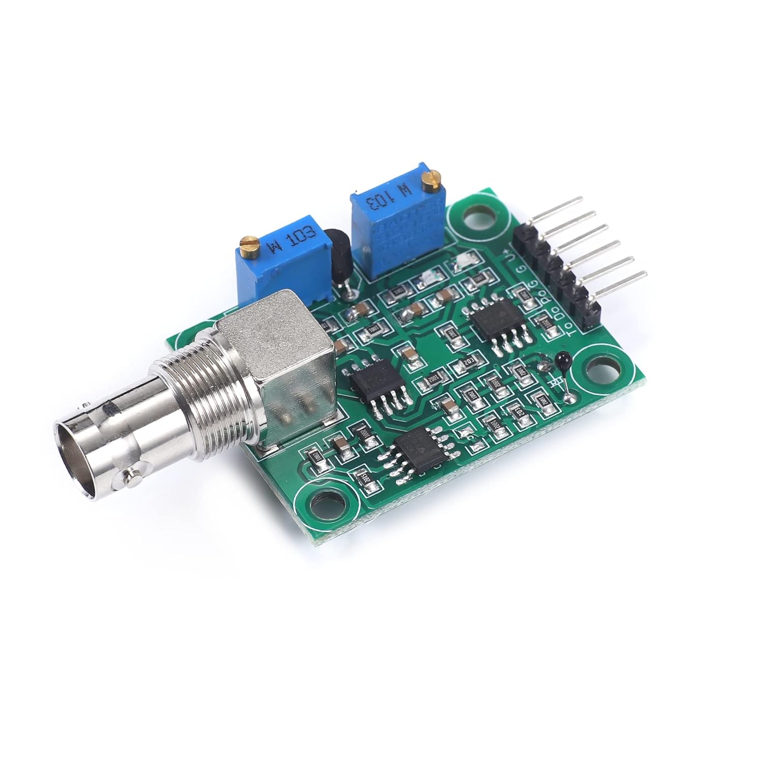
Image 2.3: Front view of the sensor module, highlighting the BNC connector for the pH probe and the two adjustment potentiometers.

Image 2.4: Interface description of the sensor module, showing pin labels (Temperature compensation, Temperature output, Level signal output, PH value output, Signal ground, Power positive, Power negative) and potentiometer labels (Reference adjustment potentiometer, Threshold adjustment potentiometer).
3. Specifications
The following table details the technical specifications of the Teyleten Robot PH Value Data Detection and Acquisition Sensor Module:

Image 3.1: Detailed product parameters.
| Parameter | Value |
|---|---|
| Heating Voltage | 5 ± 0.2V (AC/DC) |
| Working Current | 5-10mA |
| Detectable Concentration Range | PH0-14 |
| Detection Temperature Range | 0-80 °C |
| Response Time | ≤5S |
| Settling Time | ≤60S |
| Component Power | ≤0.5W |
| Working Temperature | -10 ~ 50 °C (nominal 20 °C) |
| Working Humidity | 95% RH (nominal 65% RH) |
| Output Mode | Analog voltage signal output |
| Module Dimensions (L x W x H) | 42mm x 32mm x 20mm (1.65 x 1.26 x 0.79 inches) |
| Weight | 0.02 Kilograms (0.63 ounces) |
| Material | Copper |
| Mounting Holes | 4pcs M3 Mounting Holes |
4. Setup
Follow these steps to set up your PH sensor module:
- Connect the pH Probe: Carefully connect the BNC connector of the pH electrode probe to the BNC socket on the sensor module. Ensure a secure connection.
- Power Connection: Connect the module to your microcontroller (e.g., Arduino) using the appropriate pins. The module requires a 5V power supply. Refer to Image 2.4 for pin labels:
- Power positive: Connect to 5V (VCC) on your microcontroller.
- Power negative: Connect to GND on your microcontroller.
- PH value output: Connect to an analog input pin on your microcontroller (e.g., A0 on Arduino).
- Signal ground: Connect to GND on your microcontroller.
- Temperature compensation output (optional): If your application requires temperature compensation, connect this pin to another analog input.
- Initial Power-Up: Once connections are secure, power on your microcontroller. The module should receive power.
5. Operating Instructions
After successful setup, the module will output an analog voltage signal corresponding to the pH level. This signal needs to be read by your microcontroller's Analog-to-Digital Converter (ADC) and then converted into a pH value using a suitable algorithm.
- Software Integration: Write or adapt code for your microcontroller to read the analog voltage from the 'PH value output' pin.
- Data Conversion: The analog voltage typically ranges from 0V to 5V (or 0V to 3.3V depending on your microcontroller's ADC reference). This voltage needs to be mapped to the pH scale (0-14). This mapping often requires calibration.
- Temperature Compensation: For accurate pH readings, especially across varying temperatures, utilize the temperature compensation output if available and integrate it into your pH calculation algorithm.
6. Calibration
Accurate pH measurement requires proper calibration of the sensor module. This process typically involves using known pH buffer solutions.
- Prepare Buffer Solutions: Obtain standard pH buffer solutions (e.g., pH 4.0, pH 7.0, pH 10.0). Ensure they are fresh and at a stable temperature.
- Initial Setup: Connect the pH probe to the module and the module to your microcontroller. Power on the system.
- pH 7.0 Calibration (Neutral Point):
- Immerse the pH electrode in the pH 7.0 buffer solution.
- Allow the reading to stabilize.
- Adjust the 'Reference adjustment potentiometer' (labeled on Image 2.4) on the module until the analog output corresponds to the neutral pH (e.g., 2.5V for a 0-5V range, or the specific voltage your code expects for pH 7.0).
- Slope Calibration (Acidic/Alkaline Point):
- Rinse the pH electrode thoroughly with distilled water.
- Immerse the pH electrode in either a pH 4.0 (acidic) or pH 10.0 (alkaline) buffer solution.
- Allow the reading to stabilize.
- Adjust the 'Threshold adjustment potentiometer' (labeled on Image 2.4) until the analog output accurately reflects the pH of the buffer solution. This potentiometer adjusts the slope of the pH response.
- Verification: After calibration, rinse the probe and test it in all three buffer solutions (pH 4.0, 7.0, 10.0) to verify accuracy across the range. Repeat calibration if necessary.
Note: Some users report challenges in achieving stable and accurate readings across the full pH range with a single calibration. Fine-tuning in software may be required, or focusing calibration on the specific pH range of interest for your application.
7. Maintenance
Proper maintenance extends the life and accuracy of your pH sensor module:
- Electrode Storage: Always store the pH electrode in its protective cap with a suitable storage solution (e.g., KCl solution or pH 7 buffer). Never store it dry or in distilled water, as this can damage the electrode.
- Cleaning: Regularly clean the pH electrode bulb with distilled water. For stubborn deposits, consult specific pH electrode cleaning solutions. Avoid abrasive cleaning.
- Electrode Life: pH electrodes have a limited lifespan and will eventually need replacement. Signs of a failing electrode include slow response, unstable readings, or inability to calibrate.
- Rechargeable vs. Non-Rechargeable Probes:

Image 7.1: Explanation of rechargeable and non-rechargeable pH probe differences.
The provided pH probe is typically a non-rechargeable composite electrode. While simpler to maintain, its accuracy may decrease over long-term continuous use as the KCl concentration at the liquid junction depletes. If not in use, it should be immersed in a pH electrode soaking solution to preserve performance.
8. Troubleshooting
If you encounter issues with your PH sensor module, consider the following troubleshooting steps:
- Unstable Readings:
- Ensure the pH electrode is properly immersed and free from air bubbles.
- Check for electrical noise in your setup. Keep signal wires away from power lines.
- Verify power supply stability.
- Recalibrate the sensor with fresh buffer solutions.
- Inspect the pH electrode for damage or contamination.
- Incorrect Readings:
- Perform a full two-point or three-point calibration.
- Ensure buffer solutions are accurate and not expired.
- Verify your software's pH conversion algorithm.
- Check the temperature compensation if used, as temperature significantly affects pH.
- No Output/Module Not Responding:
- Check all wiring connections for looseness or incorrect pin assignments.
- Verify the power supply to the module (5V).
- Ensure the BNC connector is securely attached to both the probe and the module.
- Test the analog input pin on your microcontroller with a known voltage source.
- Difficulty Calibrating Potentiometers:
- Some users report that the potentiometers may have limited adjustment range. If you cannot achieve the desired voltage for pH 7.0 or the correct slope, consider adjusting the offset and slope in your microcontroller's software.
- Ensure you are using the correct potentiometer for the intended adjustment (Reference for neutral point, Threshold for slope).
9. Schematic Diagram
For advanced users and integration purposes, the schematic diagram of the PH sensor module is provided below:

Image 9.1: PH sensor module schematic diagram.


