
Introduction
The hobbyant EQKIT KM-1 is a DIY kit designed for controlling the speed of DC motors using Pulse Width Modulation (PWM). This kit allows for stepless speed adjustment from zero to maximum motor speed, making it suitable for various electronic projects and applications requiring precise motor control. The circuit board and components are selected for reliability and stability, ensuring a successful assembly experience.
Product Overview and Package Contents
The KM-1 kit includes all necessary components for assembling a functional PWM motor speed controller. Please verify that all items listed below are present in your package.
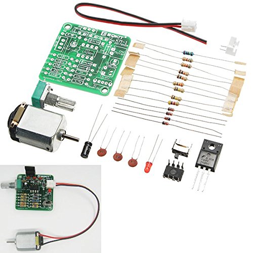
Figure 1: All components of the KM-1 DIY kit.
- 1 x KM-1 DC 6-12V PWM Motor Speed Controller PCB
- 1 x DC Motor
- 1 x Potentiometer (for speed adjustment)
- Resistors (various values)
- Capacitors
- Diodes
- Integrated Circuit (IC)
- MOSFET
- LED (Power indicator)
- Connectors and Wires
Specifications
| Feature | Specification |
|---|---|
| Model | KM-1 |
| Operating Voltage | DC 6-12V |
| PCB Board Size | 40 x 40mm |
| Control Method | PWM (Pulse Width Modulation) |
| Speed Adjustment | Stepless, from zero to maximum speed |
Circuit Description
The KM-1 motor speed controller utilizes Pulse Width Modulation (PWM) to regulate the speed of a DC motor. PWM works by rapidly switching the power to the motor on and off. The motor's average voltage, and thus its speed, is controlled by adjusting the duration of the "on" time (pulse width) relative to the total period of the pulse (duty cycle).
A wider "on" pulse (higher duty cycle) results in a higher average voltage supplied to the motor, causing it to spin faster. Conversely, a narrower "on" pulse (lower duty cycle) reduces the average voltage, leading to slower motor speeds. The potentiometer allows for continuous adjustment of this duty cycle, providing stepless speed control.

Figure 2: KM-1 PCB with component markings.
Setup and Assembly Instructions
Follow these steps carefully to assemble your KM-1 PWM motor speed controller kit. Ensure you have basic soldering tools and skills before proceeding.
Step 1: Identify Components
Before soldering, familiarize yourself with all the components. Refer to Figure 1 and the component list. The PCB has markings indicating where each component should be placed.
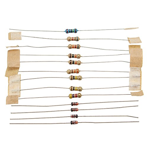
Figure 3: Resistors and Diodes.
Step 2: Solder Resistors and Diodes
Start by soldering the smallest components first. Insert the resistors and diodes into their designated positions on the PCB, matching the values and polarity (for diodes). Bend the leads to hold them in place, then solder and trim excess leads.
- Resistors: Match the color bands to the values indicated on the PCB (e.g., R1, R2, etc.).
- Diodes: Ensure the stripe on the diode matches the stripe marking on the PCB.
Step 3: Solder Capacitors
Next, solder the capacitors. Pay attention to polarity for electrolytic capacitors (usually marked with a stripe for the negative lead). Ceramic capacitors typically do not have polarity.
- Electrolytic Capacitors: Match the negative stripe on the capacitor to the corresponding marking on the PCB (e.g., C1).
- Ceramic Capacitors: Can be inserted in either orientation (e.g., C2, C3).
Step 4: Solder IC and MOSFET
Carefully insert the Integrated Circuit (IC) and the MOSFET into their respective positions. Ensure the orientation is correct. The IC usually has a notch or dot indicating Pin 1, which should align with the marking on the PCB. The MOSFET has a specific shape that matches the PCB footprint.
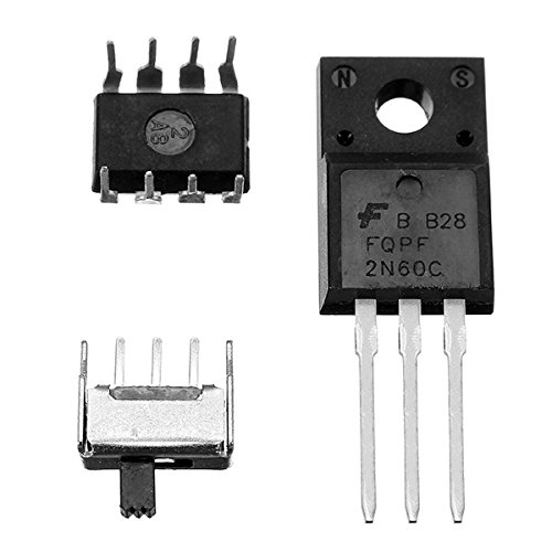
Figure 4: IC and MOSFET components.
- IC (LM2904): Align the notch/dot with the PCB marking.
- MOSFET (2N60C): Match the component shape to the PCB outline (e.g., Q1).
Step 5: Solder Potentiometer and LED
Solder the potentiometer and the LED. The LED is a polarized component; its longer lead is typically positive (+). The PCB will have markings for LED polarity.
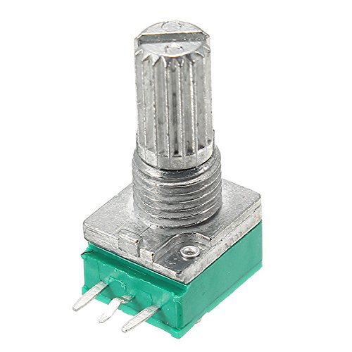
Figure 5: Potentiometer for speed control.
- Potentiometer (VR1): Insert into the designated three-pin header.
- LED (D3/POW LED): Ensure the longer lead (anode) goes into the positive (+) hole.
Step 6: Connect Motor and Power Wires
Connect the DC motor to the "Motor" terminals (CN2) on the PCB. Connect the power input wires to the "DC 6V" terminals (S1/Power SW), ensuring correct polarity (positive to + and negative to -).
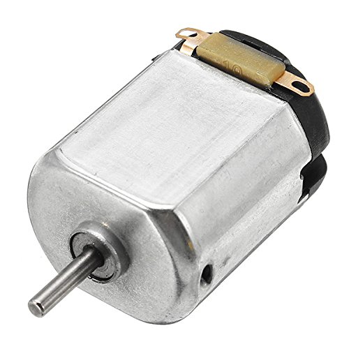
Figure 6: DC Motor.
- Motor Connection: Solder the motor leads to the CN2 pads. Polarity for the motor will determine rotation direction.
- Power Input: Solder the power supply wires to the S1 pads, observing polarity.
Double-check all solder joints for shorts or cold joints. Ensure all components are correctly oriented before applying power.
Operating Instructions
- Power On: Connect a DC power supply (6-12V) to the power input terminals (S1). The power LED (D3) should illuminate.
- Adjust Speed: Rotate the knob on the potentiometer (VR1) to adjust the motor speed. Turning it in one direction will increase the speed, while turning it in the opposite direction will decrease it.
- Observe Motor: The connected DC motor should respond to the potentiometer adjustments, changing its rotational speed accordingly.
- Power Off: Disconnect the power supply when not in use.
The controller provides stepless speed adjustment, allowing for fine-tuning of the motor's rotational speed.
Maintenance
- Keep the circuit board clean and free from dust and debris.
- Avoid exposing the circuit to moisture or extreme temperatures.
- Periodically check solder joints for any signs of cracking or corrosion, especially if the device is subjected to vibrations.
- The potentiometer is designed for long-term use and is resistant to dust and oxidation, but gentle handling is always recommended.
Troubleshooting
- Motor does not spin:
- Check power supply connection and ensure it is within the 6-12V DC range.
- Verify power LED (D3) is illuminated. If not, check power input polarity and connections.
- Inspect motor connections (CN2) for proper soldering and polarity.
- Ensure the potentiometer is not set to the minimum (zero speed) position.
- Check for any short circuits or cold solder joints on the PCB.
- Motor speed is erratic or uncontrollable:
- Check the potentiometer for proper connection and function.
- Inspect solder joints around the IC and MOSFET for any issues.
- Ensure the power supply is stable and providing consistent voltage.
- No power LED:
- Verify power supply is connected and functional.
- Check the polarity of the power input.
- Ensure the LED is correctly oriented (polarity) and properly soldered.
Warranty and Support
Information regarding warranty and customer support for the hobbyant EQKIT KM-1 is not provided in the product details. For assistance, please refer to the retailer or manufacturer's website where the product was purchased.