
1. Introduction
This manual provides detailed instructions for the assembly, operation, and maintenance of the DIYElectronic DC 5V Music Circuit LED Flashing Module Kit. This kit is designed for educational purposes, electronic training, and enthusiasts interested in understanding basic electronic circuits and their applications.
The module utilizes a CD4060 14-level binary counter with an internal oscillation circuit to control 12 red, yellow, and green LEDs, creating a flashing light effect. A music component is integrated to produce sound, synchronized with the LED activity. The flashing frequency can be adjusted via a variable resistor.
2. Kit Components
Before beginning assembly, please verify that all components listed below are present in your kit. Refer to the image for visual identification of the components.

Image 2.1: Overview of all electronic components included in the kit, neatly arranged for identification.
- Printed Circuit Board (PCB)
- CD4060 IC (Integrated Circuit)
- IC Socket (for CD4060)
- Resistors (various values: 200Ω, 9012, 10KΩ, 1MΩ, 220KΩ)
- Capacitors (1µF electrolytic, 1µF ceramic)
- LEDs (12 pieces: red, yellow, green)
- Transistors (Q1, Q2, Q3, Q4 - likely S9012 or similar)
- Diodes (D1, D2, D3, D4 - likely 4007, 4148)
- Buzzer/Speaker (LS)
- Power Input Terminal (J1)
- Push Button Switch (S1)
- Potentiometer (variable resistor for R3 adjustment)
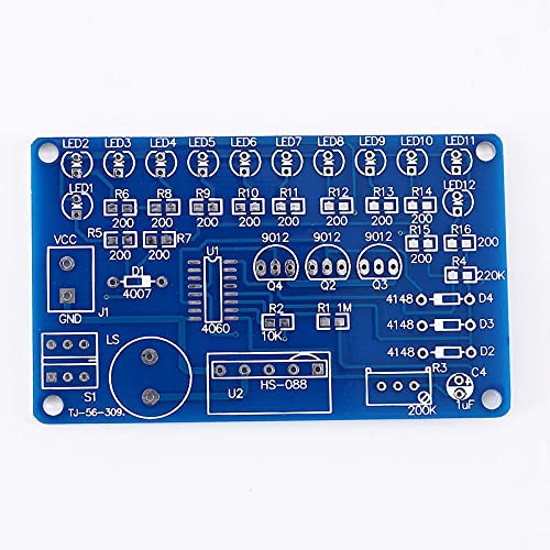
Image 2.2: The Printed Circuit Board (PCB) showing component placement guides and labels.
3. Assembly Instructions
Follow these steps carefully to assemble your Music Circuit LED Flashing Module. Soldering skills are required.
- Prepare the PCB: Inspect the Printed Circuit Board (PCB) for any defects. Familiarize yourself with the component placement markings on the PCB.
- Install Resistors: Solder all resistors (R1-R16) into their designated positions on the PCB. Resistors are not polarized, but ensure the correct resistance value is placed at each location.
- Install Diodes: Solder diodes D1, D2, D3, D4. Pay close attention to the polarity. The band on the diode must match the band marking on the PCB.
- Install IC Socket: Solder the IC socket for the CD4060. Ensure the notch on the socket aligns with the notch marking on the PCB. Do not insert the CD4060 IC yet.
- Install Capacitors: Solder the capacitors. For electrolytic capacitors (larger cylindrical ones), observe polarity: the longer lead is positive (+), and the shorter lead (or marked side) is negative (-). Match this to the PCB markings. Ceramic capacitors are not polarized.
- Install Transistors: Solder transistors Q1, Q2, Q3, Q4. Match the flat side of the transistor to the flat side indicated on the PCB silkscreen.
- Install LEDs: Solder the 12 LEDs (LED1-LED12). LEDs are polarized. The longer lead is the anode (+), and the shorter lead is the cathode (-). Match the longer lead to the '+' marking or the square pad on the PCB.
- Install Buzzer/Speaker: Solder the buzzer (LS) into its position.
- Install Switch and Potentiometer: Solder the push-button switch (S1) and the potentiometer (variable resistor R3) into their respective places.
- Install Power Terminal: Solder the power input terminal (J1).
- Insert CD4060 IC: Carefully insert the CD4060 IC into its socket. Ensure the notch on the IC aligns with the notch on the socket and the PCB. Bend the pins slightly inward if necessary to fit, but avoid excessive force.
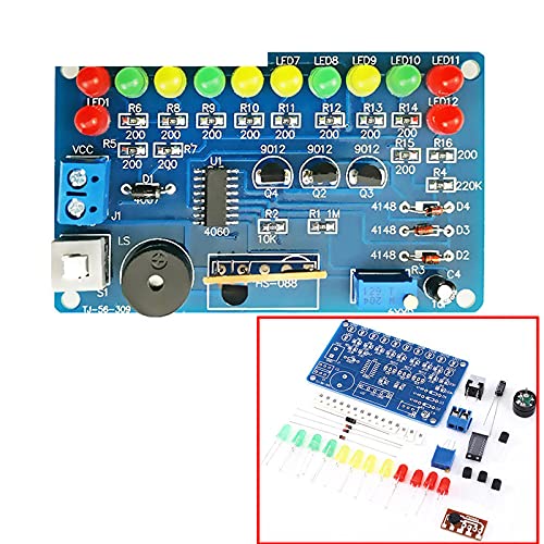
Image 3.1: An example of the fully assembled module, ready for operation.
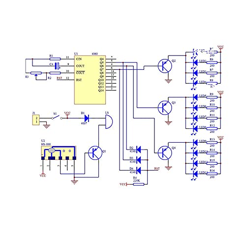
Image 3.2: Circuit diagram illustrating the connections and logic of the module.
4. Operating Instructions
Once assembled, the module is ready for operation.
- Power Connection: Connect a DC 5V power supply to the power input terminal (J1). Ensure correct polarity: VCC (positive) and GND (negative). The module operates within a voltage range of 4.5V to 5V DC.
- Initial Operation: Upon power-up, the LEDs should begin flashing, and the integrated music component will emit sound.
- Adjusting Flashing Speed: Use a small screwdriver to carefully turn the potentiometer (R3). Turning R3 will change the frequency of the RC oscillator circuit, thereby adjusting the blinking speed of the LEDs and potentially the tempo of the music.
- Reset Function: The circuit incorporates a reset mechanism. When specific conditions are met (Q5-Q7 outputs of the CD4060 are high), the CD4060 is reset, causing the LEDs to momentarily turn on before the counting sequence restarts.
5. Specifications
- Operating Voltage: 4.5V - 5V DC
- Main IC: CD4060 (14-level binary counter with oscillator)
- LEDs: 12 (Red, Yellow, Green)
- Material: FR-4 Glass Plate (PCB)
- Application: Vocational college electronic skills training, electronic training, electronic enthusiast learning.
6. Troubleshooting
If the module does not function as expected after assembly, consider the following common issues:
- No Power/No Lights:
- Check power supply connections and ensure it provides 5V DC.
- Verify power input polarity (VCC and GND).
- Inspect all solder joints for cold joints or bridges.
- Ensure the CD4060 IC is correctly seated in its socket and oriented properly.
- LEDs Not Flashing Correctly:
- Check the polarity of all LEDs.
- Verify the correct placement and value of resistors, especially those connected to LEDs.
- Adjust the potentiometer (R3) to see if it affects the flashing speed.
- No Sound:
- Check the connections and polarity of the buzzer/speaker.
- Ensure the transistor driving the buzzer is correctly installed.
- Component Overheating:
- Immediately disconnect power.
- Check for short circuits, incorrect component placement, or reversed polarity of polarized components (diodes, electrolytic capacitors, IC).
7. Maintenance
This electronic kit requires minimal maintenance to ensure longevity and proper function.
- Cleaning: Keep the module free from dust and debris. Use a soft, dry brush or compressed air to clean the PCB. Avoid using liquids.
- Storage: Store the module in a dry environment, away from direct sunlight and extreme temperatures.
- Handling: Handle the assembled module with care to avoid bending or breaking components, especially the LEDs and wires.
8. Warranty and Support
Specific warranty information for this DIY kit is not provided. For any issues, technical support, or inquiries regarding missing components, please contact the seller directly through your purchase platform. As this is a DIY kit, successful assembly and operation depend on the user's soldering skills and adherence to instructions.