
DIYElectronic CAI-201
DC 5V RGB 4Bit Digital Electronic Clock DIY Kit User Manual
Model: CAI-201
1. Introduction
The CAI-201 is a DC 5V RGB 4Bit Digital Electronic Clock DIY Kit designed for displaying real-time date, time, and temperature. This kit allows users to assemble their own functional clock with alarm capabilities. Its design makes it suitable for various home or office environments.
Key Features:
- RGB auto color change
- Automatic brightness adjustment
- Time/Date/Alarm/Temperature display
- 12H or 24H hourly optional system
- Time memory function
- Temperature calibration capability
- Voice Hourly Report function
- Designed for DIY manual soldering
- Simple and easy to operate
Technical Parameters:
- Model: CAI-201
- Work Voltage: DC 5V
- Work Temperature: -40℃~85℃
- Work Humidity: 0%~95%RH
- Size (Installed): 115mm x 40mm x 32mm (Length x Width x Height)
2. Package Contents
Upon opening the package, please verify that all components listed below are present and undamaged. If any items are missing or damaged, please contact customer support.
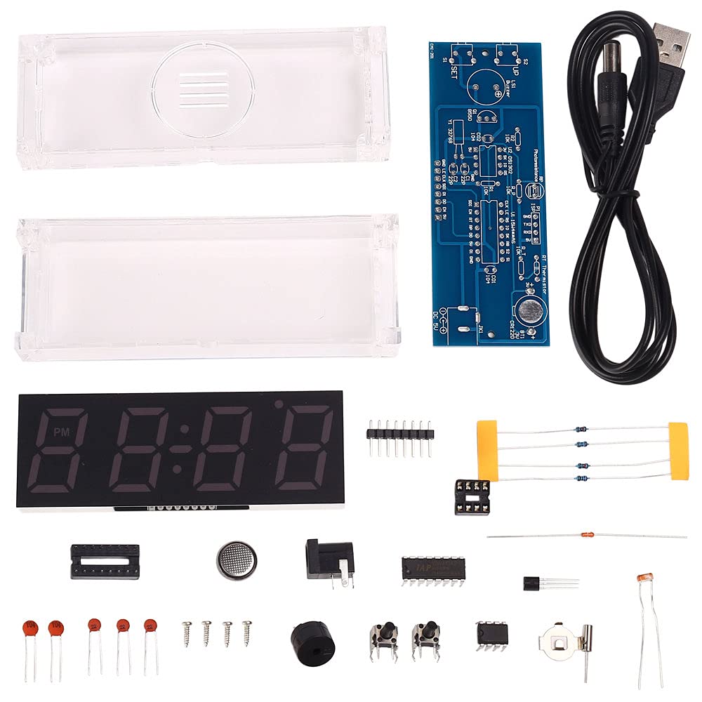
Image: All components included in the DIY Electronic Clock Kit. This includes the PCB, USB power cable, 4-bit display, various resistors, sensors, buttons, and other electronic parts necessary for assembly.
The kit typically includes:
- Main PCB (Printed Circuit Board)
- 4-Bit Digital Display Module
- Acrylic Casing Components
- USB Power Cable
- Temperature Sensor (NTC Thermistor)
- Photoresistor Sensor (Light Sensor)
- Control Buttons (UP, SET)
- Buzzer
- Various Resistors, Capacitors, Diodes, and Integrated Circuits
- Mounting Hardware (Screws, standoffs)
3. Assembly Instructions (DIY Kit)
This product is a DIY kit and requires manual soldering and assembly. Basic soldering skills and tools are necessary. Please follow these steps carefully.
3.1. Component Identification
Before starting, familiarize yourself with all components. Refer to the PCB silkscreen for component placement and polarity markings.
3.2. Soldering Process
- Solder Smaller Components First: Begin by soldering low-profile components such as resistors, diodes, and small capacitors. Pay attention to polarity for diodes and electrolytic capacitors.
- Install IC Sockets (if applicable): If the kit includes IC sockets, solder them before inserting the actual ICs. This protects the ICs from heat during soldering.
- Solder Larger Components: Proceed with larger components like the buzzer, buttons, and sensors.
- Connect Display Module: Carefully solder the 4-bit digital display module to the designated pins on the PCB. Ensure all pins are correctly aligned and soldered.
- Solder Power Jack/USB Connector: Attach the power input connector.
- Inspect Solder Joints: After soldering all components, carefully inspect each joint for cold solder joints, bridges, or poor connections. Re-solder as necessary.
3.3. Casing Assembly
Once the electronic assembly is complete and tested, proceed with assembling the acrylic casing.

Image: The fully assembled DC 5V RGB 4Bit Digital Electronic Clock, displaying time in a clear acrylic casing.
- Remove Protective Films: Peel off any protective films from the acrylic panels.
- Assemble Base and Sides: Carefully fit the side panels into the base panel.
- Insert PCB Assembly: Slide the soldered PCB assembly into the grooves or designated area within the casing.
- Attach Top Panel: Secure the top panel, ensuring all components fit correctly and buttons align with their openings.
- Secure with Screws: Use the provided screws to fasten the casing panels together. Do not overtighten.
4. Operating Instructions
Once assembled, connect the clock to a DC 5V power source using the provided USB cable. The clock will power on and display the current time or default settings.
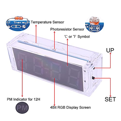
Image: A side view of the assembled clock, highlighting the 'UP' and 'SET' buttons, the PM indicator, the 4Bit RGB Display Screen, and the locations of the Temperature Sensor and Photoresistor Sensor. This image helps identify key interaction points and features.
4.1. Button Functions
- SET Button: Used to enter settings mode and cycle through different setting parameters (Time, Date, Alarm, Temperature Calibration, Display Mode, etc.). A short press typically moves to the next setting, while a long press might save settings or exit a mode.
- UP Button: Used to adjust values within a setting mode (e.g., incrementing hours, minutes, or date). In normal display mode, it might cycle through display options or activate/deactivate certain features.
4.2. Setting Time and Date
- Press and hold the SET button until the display changes, indicating entry into time setting mode (e.g., hours flashing).
- Use the UP button to adjust the hour.
- Press the SET button again to move to minutes, then use UP to adjust.
- Continue pressing SET to cycle through year, month, and day settings, adjusting each with the UP button.
- After setting the date, press SET to save and exit, or to move to the next setting option (e.g., 12/24H format).
4.3. Setting Alarm
- From normal display, press SET repeatedly until you reach the alarm setting mode (e.g., "AL" or alarm time flashing).
- Use the UP button to set the desired alarm hour.
- Press SET to move to alarm minutes, then use UP to adjust.
- Press SET again to enable/disable the alarm (ON/OFF).
- Press SET to save and exit.
4.4. Temperature Display and Calibration
The clock displays temperature automatically. If calibration is needed:
- Enter settings mode using the SET button until you reach the temperature calibration option (e.g., "TEMP CAL").
- Use the UP button to adjust the temperature offset.
- Press SET to save and exit.
4.5. RGB Color and Brightness Adjustment
The clock features automatic RGB color change and brightness adjustment based on ambient light (via photoresistor). Specific manual adjustments may be available through the settings menu, depending on the firmware version.
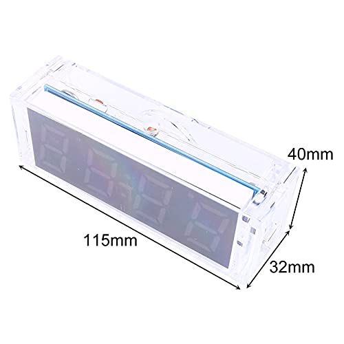
Image: The digital clock displaying the time '7:23' with segments illuminated in various RGB colors, demonstrating its color-changing capability.
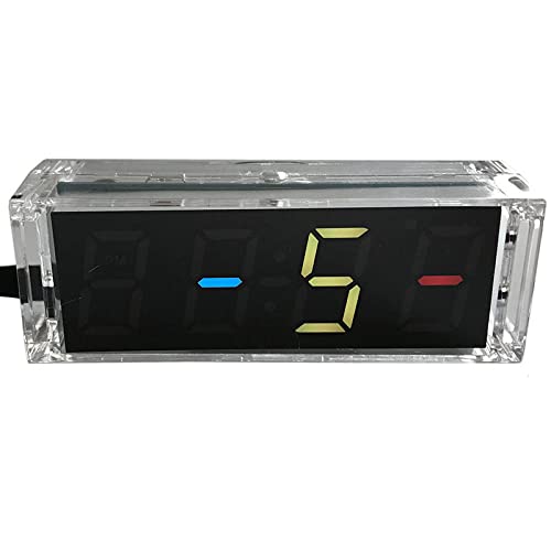
Image: The digital clock displaying a date or numerical sequence '8-5-' with segments illuminated in various RGB colors, showcasing the display's versatility.
5. Maintenance
The DC 5V RGB 4Bit Digital Electronic Clock DIY Kit is designed for low maintenance. Follow these guidelines to ensure longevity:
- Cleaning: Use a soft, dry cloth to clean the acrylic casing. Avoid abrasive cleaners or solvents that may damage the plastic.
- Power Supply: Always use a stable DC 5V power supply. Avoid using power sources with fluctuating voltage or current.
- Environment: Keep the clock in a dry environment, away from direct sunlight, extreme temperatures, and high humidity.
- Handling: Handle the assembled clock with care to prevent damage to the electronic components or casing.
6. Troubleshooting
| Problem | Possible Cause | Solution |
|---|---|---|
| Clock does not power on. | No power supply; faulty USB cable; incorrect soldering; short circuit. | Ensure 5V power is connected. Test with another USB cable. Inspect all solder joints for continuity and shorts. |
| Display is dim or erratic. | Insufficient power; faulty display module; poor connection to display. | Verify power supply. Check display module soldering. Ensure photoresistor is not obstructed. |
| Buttons are unresponsive. | Buttons not soldered correctly; faulty buttons; incorrect casing assembly. | Check button solder joints. Ensure buttons are not jammed by the casing. |
| Incorrect time/date. | Time/date not set; battery for memory function is low/missing (if applicable). | Follow "Setting Time and Date" instructions. Check if a backup battery is required and installed correctly. |
| Temperature reading is inaccurate. | Temperature sensor faulty; needs calibration. | Calibrate the temperature using the settings menu. Ensure the sensor is not covered or exposed to external heat sources. |
7. Specifications
Detailed technical specifications for the CAI-201 RGB 4Bit Digital Electronic Clock DIY Kit:
- Product Name: CAI-201 RGB 4Bit Digital Electronic Clock DIY Kit
- Model: CAI-201
- Input Voltage: DC 5V
- Operating Temperature: -40℃ to 85℃ (-40°F to 185°F)
- Operating Humidity: 0% to 95% RH (non-condensing)
- Dimensions (Assembled): 115mm (Length) x 40mm (Width) x 32mm (Height)
- Display Type: 4-Bit Digital LED, RGB Color
- Time Format: 12-Hour or 24-Hour selectable
- Functions: Time, Date, Temperature, Alarm, Voice Hourly Report, Automatic Brightness, RGB Auto Color Change, Time Memory
- Material: Acrylic Casing, Electronic Components (PCB, ICs, etc.)
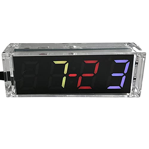
Image: A diagram showing the dimensions of the assembled clock: 115mm in length, 40mm in width, and 32mm in height. This provides precise measurements for placement and understanding the product's physical size.
8. Warranty and Support
This DIY kit is provided with components as described. Due to the nature of DIY assembly and soldering, warranty coverage typically applies to defective components upon receipt, not to issues arising from incorrect assembly or handling.
For technical support, component replacement, or inquiries regarding the kit, please contact the manufacturer or seller through the platform where the product was purchased. Provide your order number and a detailed description of the issue for prompt assistance.
Manufacturer: DIYElectronic
Ask a question about this manual
Ask about setup, troubleshooting, compatibility, parts, safety, or missing instructions. Manuals+ will review the question and use this page’s manual context to help answer it.