
1. Introduction
This manual provides detailed instructions for the DIYElectronic STM32F103C8T6 Development Board. This board is designed for embedded system development, featuring the STM32F103C8T6 microcontroller. It offers various interfaces and features suitable for a wide range of applications, from hobby projects to professional prototyping.
2. Package Contents
Upon opening the package, please verify that all the following components are present and in good condition:
- 1x STM32F103C8T6 Development Board
- 1x 80cm USB Data Cable
- 2x 20-Pin Male Pin Headers
- 1x 11-Pin Female Pin Header
- 1x 5-Pin Male Pin Header

Figure 2.1: The STM32F103C8T6 Development Board along with the USB data cable and various pin headers included in the package.
3. Features
The STM32F103C8T6 Development Board offers the following key features:
- Microcontroller: STM32F103C8T6 (ARM Cortex-M3)
- USB Connectivity: Supports USB one-key download for easy programming.
- Display Support: Compatible with 1.44-inch and 1.8-inch TFT LCD screens, and OLED LCD screens.
- GPIO Pins: All microcontroller pins are exposed for flexible interfacing.
- Indicators: Equipped with work LED indicators (D1, D2) for status feedback.
- Buttons: Includes K0 (User) and Reset buttons.
- Power Supply: Operates with DC 3.3V/5V.
- Data Storage: Integrated 24C04 EEPROM for data storage.
- Crystal Oscillators: Features an 8MHz high-speed crystal oscillator and a 32.768KHz low-frequency crystal oscillator.
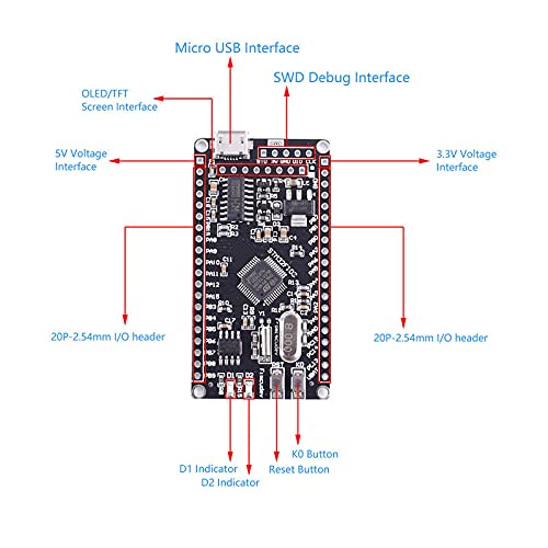
Figure 3.1: Overview of the STM32F103C8T6 Development Board highlighting key interfaces such as Micro USB, SWD Debug, 5V/3.3V Voltage, OLED/TFT Screen Interface, I/O headers, and buttons.
4. Setup Guide
Follow these steps to set up your STM32F103C8T6 Development Board:
- Inspect the Board: Before connecting power, visually inspect the development board for any physical damage or loose components.
- Connect Pin Headers: If required for your project, solder the provided male and female pin headers to the appropriate locations on the board. Ensure proper orientation.
- Power Connection: Connect the board to a power source using the provided USB data cable. The board can be powered via the Micro USB interface. A 5V power supply is typically provided by the USB port.
- Driver Installation: For initial use, you may need to install USB drivers for the STM32 microcontroller on your computer. Refer to the official STMicroelectronics website or your chosen IDE's documentation for specific driver installation instructions.
- IDE Setup: Install a suitable Integrated Development Environment (IDE) such as Keil MDK, STM32CubeIDE, or PlatformIO. Configure the IDE to recognize the STM32F103C8T6 microcontroller.
- First Program Upload: Connect the USB cable to your computer and the board. Use the "one-key download" feature or your IDE's programming tools to upload a simple test program (e.g., blinking an LED) to verify functionality.
5. Operating Instructions
This section outlines general operating procedures for the STM32F103C8T6 Development Board.
5.1 Programming the Microcontroller
- USB One-Key Download: The board supports direct program upload via the Micro USB port. Ensure your IDE is configured for this method.
- SWD Debug Interface: For advanced debugging and programming, connect an SWD (Serial Wire Debug) programmer/debugger to the dedicated SWD Debug Interface pins on the board.
- Boot Mode Selection: The board typically has boot mode selection jumpers (BOOT0, BOOT1) to choose between Flash memory, System memory (bootloader), or SRAM for booting. Refer to the STM32F103C8T6 datasheet for specific configurations.
5.2 Connecting Peripherals
- GPIO Pins: Utilize the exposed 20-pin I/O headers on both sides of the board to connect external sensors, actuators, and other modules. Refer to the STM32F103C8T6 datasheet and board schematic for pin assignments.
- Display Modules: Connect 1.44-inch/1.8-inch TFT LCD or OLED screens to the dedicated display interface pins. Ensure correct pin mapping (SPI, I2C, etc.) as per your display module's specifications.
- Powering External Components: The board provides 3.3V and 5V power output pins. Use these to power compatible external components, ensuring not to exceed the maximum current draw.
6. Maintenance
Proper maintenance ensures the longevity and reliable operation of your development board.
- Storage: Store the board in an anti-static bag when not in use to prevent electrostatic discharge (ESD) damage. Keep it in a dry environment, away from direct sunlight and extreme temperatures.
- Cleaning: If necessary, gently clean the board with a soft, dry brush or compressed air to remove dust. Avoid using liquids or abrasive materials.
- Handling: Always handle the board by its edges to minimize contact with components and prevent ESD.
- Power Off: Disconnect power before making any physical connections or disconnections to the board or its peripherals.
7. Troubleshooting
This section addresses common issues you might encounter.
- Board Not Powering On:
- Ensure the USB cable is securely connected to both the board and a working USB port on your computer or power adapter.
- Check if the USB port provides sufficient power (typically 5V).
- Verify that the power indicator LED on the board illuminates.
- Computer Not Recognizing the Board:
- Install or update the necessary USB drivers for the STM32 microcontroller.
- Try a different USB port or cable.
- Restart your computer.
- Program Upload Failure:
- Ensure your IDE is correctly configured for the STM32F103C8T6 and the selected programming method (e.g., USB DFU, SWD).
- Check boot mode jumper settings if applicable.
- Verify that the program code is free of errors and compiles successfully.
- Ensure no other software is using the serial port connected to the board.
- Peripheral Not Working:
- Double-check all wiring connections between the board and the peripheral.
- Verify that the peripheral is correctly powered.
- Ensure your code correctly initializes and communicates with the peripheral (e.g., correct SPI/I2C addresses, pin assignments).
8. Specifications
Detailed technical specifications for the STM32F103C8T6 Development Board:
| Parameter | Value |
|---|---|
| Product Name | STM32F103C8T6 Development Board |
| Work Voltage | DC 3.3V/5V |
| Data Storage | 24C04 EEPROM |
| High-Speed Crystal Oscillator | 8MHz |
| Low-Frequency Crystal Oscillator | 32.768KHz |
| Operating Temperature | -20℃ ~ 85℃ |
| Operating Humidity | 5% ~ 95%RH |
| Module Size (L*W*H) | 60mm * 32mm * 7mm |
| Connectivity Technology | USB |
| Operating System (Example) | FreeRTOS (Supported) |
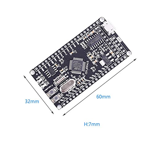
Figure 8.1: Physical dimensions of the STM32F103C8T6 Development Board, measuring 60mm in length, 32mm in width, and 7mm in height.
9. Warranty and Support
For warranty information and technical support, please refer to the retailer or manufacturer's official website where you purchased the DIYElectronic STM32F103C8T6 Development Board. Keep your proof of purchase for any warranty claims.
Online resources such as community forums, official documentation, and example code for the STM32F103 series microcontrollers are widely available and can be valuable for development and troubleshooting.