
1. Introduction
This manual provides detailed instructions for the installation, operation, and maintenance of the DAVITU US-52 AC Motor Speed Controller. The US-52 is designed to regulate the speed of adjustable AC induction motors, offering precise control and directional options (forward/reverse). It is suitable for various industrial applications including machine tools, textile machinery, conveying machines, and printing mechanisms.
2. Safety Information
- Electrical Hazard: This device operates on AC 220V. Ensure all power is disconnected before installation, wiring, or maintenance to prevent electric shock.
- Qualified Personnel: Installation and wiring should only be performed by qualified electricians or technicians.
- Proper Loading: The PWM controller requires a load to function correctly. Do not test without a connected motor.
- Motor Compatibility: The US-52 is specifically designed for adjustable AC induction motors. Using it with other motor types is not recommended and may cause damage or malfunction.
- Environmental Conditions: Install the controller in a dry, well-ventilated area, away from excessive heat, moisture, and corrosive substances.
3. Product Overview
The DAVITU US-52 AC Motor Speed Controller features a robust design for reliable performance. Key components include:
- Speed Control Knob: Used to adjust the motor's rotational speed from low to high.
- ON/OFF Switch: Toggles power to the motor.
- Green LED Indicator: Illuminates when the controller is powered on.
- Terminal Block: For main power input and motor connections.
- 6-Pin Connector: For connecting to the motor's control wiring.
- Filter Capacitor: Models with power ratings of 300W and 400W include a filter capacitor for enhanced performance. Lower wattage models (6W-250W) do not include this feature.
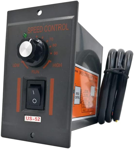
Figure 3.1: Front view of the US-52 controller, showing the speed control knob, ON/OFF switch, and power indicator.
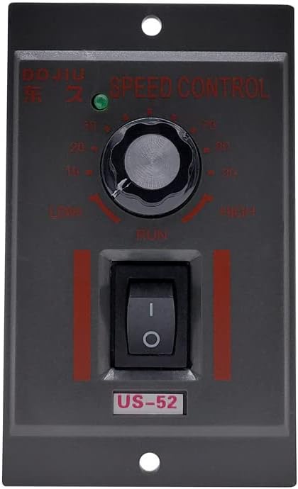
Figure 3.2: Side view illustrating the integrated wiring diagram for motor and power connections.
4. Specifications
| Feature | Description |
|---|---|
| Model | US-52 |
| Rated Voltage | AC 220V, 50Hz |
| Power Range | 6W - 400W (This specific model is 15W) |
| Connector Type | 6 Pins |
| Cable Length | 60cm |
| Control Features | Corotation/Reverse Option, Green LED Indicator, ON/OFF Switch, Speed Adjustment Knob |
| Efficiency | IE 2 |
| Certification | None |
| Material | PVC |
5. Setup and Installation
Careful wiring is essential for the correct and safe operation of the US-52 controller. Refer to the wiring diagram provided on the product and in Figure 5.1.
5.1 Wiring Connections
- Power Input: Connect the AC 220V, 50Hz power supply to the designated AC terminals on the controller's terminal block. Ensure proper polarity if indicated.
- Motor Connection: Connect your adjustable AC induction motor to the motor output terminals. The controller includes a 6-pin connector for this purpose.
- Rotation Direction (Corotation/Reverse):
- For Corotation (Forward): Connect the 'CW' (Clockwise) terminal and the 'COM' (Common) terminal.
- For Reverse (Counter-Clockwise): Connect the 'CW' (Clockwise) terminal and the 'CCW' (Counter-Clockwise) terminal.
Note: The specific wiring for these directional options is typically indicated on the controller's internal diagram or the motor's specifications. Incorrect wiring may prevent speed adjustment or stable operation.
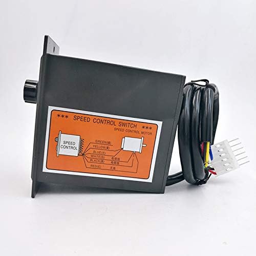
Figure 5.1: Detailed wiring diagram for connecting the speed controller to an AC induction motor.

Figure 5.2: Close-up of the terminal block, showing connections for power input and motor control.
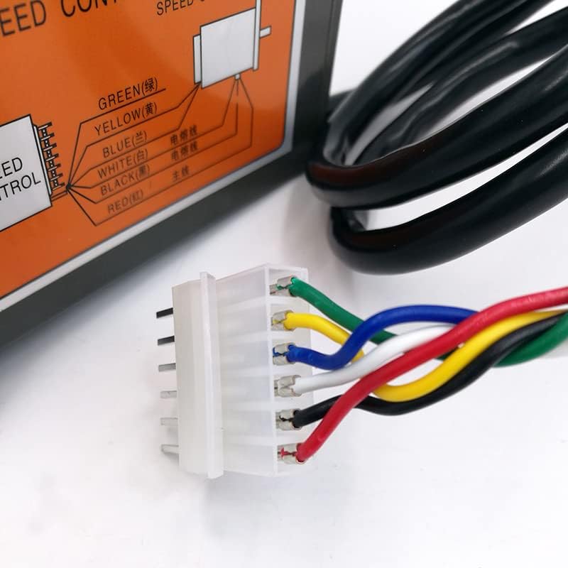
Figure 5.3: The 6-pin connector used for motor wiring, showing individual wire colors.
5.2 Pre-Operation Check
Before applying power, double-check all wiring connections to ensure they are secure and correctly configured according to the diagram. Verify that the motor is an adjustable AC induction type and that the controller is loaded with the motor.
6. Operation
- Power On: Flip the ON/OFF switch to the 'ON' position. The green LED indicator should illuminate, signifying that the controller is powered.
- Adjust Speed: Rotate the speed control knob clockwise to increase the motor speed and counter-clockwise to decrease it. The knob allows for continuous adjustment from low to high speed.
- Change Direction (if wired): If your motor is wired for directional control (CW/CCW), ensure the appropriate connection is made as described in Section 5.1. The controller itself does not have a separate switch for direction; it is determined by the wiring configuration.
- Power Off: To stop the motor, flip the ON/OFF switch to the 'OFF' position.
7. Maintenance
The DAVITU US-52 AC Motor Speed Controller is designed for durability and requires minimal maintenance. Follow these guidelines to ensure optimal performance and longevity:
- Regular Cleaning: Keep the controller free from dust and debris. Use a soft, dry cloth for cleaning. Do not use liquid cleaners or solvents.
- Inspect Connections: Periodically check all wiring connections for tightness and signs of wear or corrosion. Loose connections can lead to intermittent operation or damage.
- Environmental Check: Ensure the operating environment remains within recommended conditions (dry, well-ventilated, stable temperature).
8. Troubleshooting
If you encounter issues with your DAVITU US-52 AC Motor Speed Controller, refer to the following troubleshooting guide:
| Problem | Possible Cause | Solution |
|---|---|---|
| Motor does not run | No power supply; ON/OFF switch is off; Loose wiring connections; Controller not loaded with motor. | Check power source; Ensure switch is ON; Verify all wiring connections are secure; Connect an appropriate AC induction motor. |
| Speed is not adjustable or unstable | Incorrect motor type; Specific control wires not connected correctly (e.g., the two lines mentioned in product description); Faulty speed control knob. | Ensure motor is an adjustable AC induction type; Review wiring diagram and ensure all control wires are correctly connected; Contact support if knob is suspected faulty. |
| Motor runs in wrong direction | Incorrect CW/CCW wiring for desired rotation. | Refer to Section 5.1 and adjust the CW/CCW wiring as needed for corotation or reverse. |
| Green LED does not light up | No power supply; Controller is off; LED malfunction. | Check power source and connections; Ensure ON/OFF switch is in the 'ON' position; If power is present and switch is on, LED may be faulty. |
9. Warranty and Support
Information regarding product warranty and customer support is not provided in the available product details. Please refer to your purchase documentation or contact your retailer for specific warranty terms and support options.